camera controller
08 Feb 2011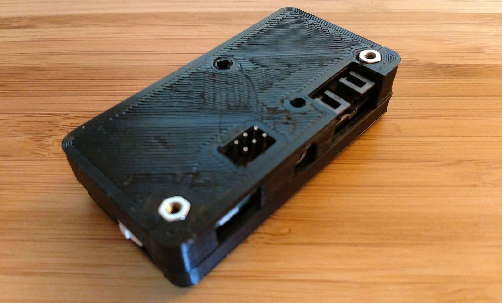
A Raspberry Pi Zero based camera controller to control a point-and-shoot camera, mirrorless or DSLR for timelapses.
Features:
- turn camera on/off
- power the camera by an external 2S lipo battery
- release shutter via 2.5mm audio jack compatible adapter cable
- release shutter via USB and a Raspberry Pi Zero for more advanced control
- power control and UART communication with the Pi Zero
- battery voltage measurement
- USB socket for changing settings via USB OTG and an android app
The camera controller can turn the camera on, power the Raspberry Pi Zero which in turn takes a picture and asks the controller to turn itself and the camera off again. This way the battery is preserved as much as possible and via PTP multiple exposures are easy.
Hardware:
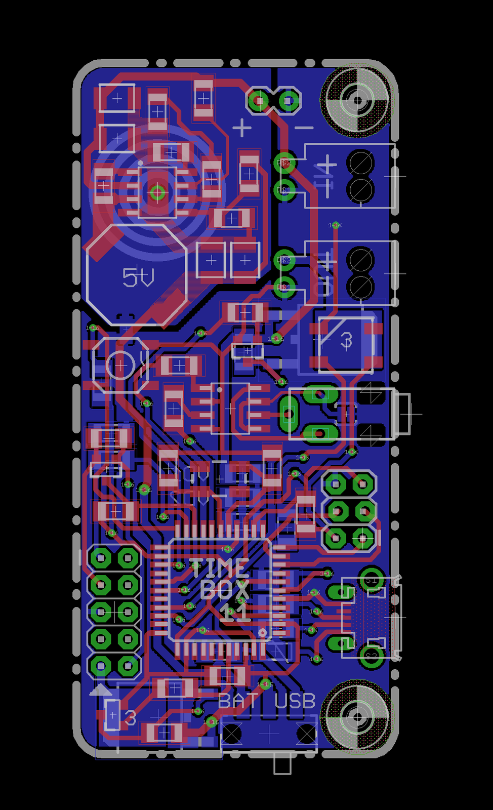
Eagle files on github.
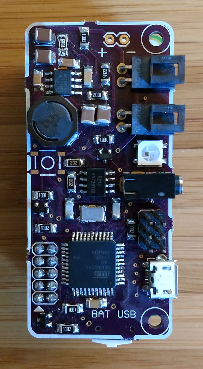
Soldering is possible by hand if you’ve got basic soldering skills. Smallest part is 1206 and to solder the legs of the microcontroller a good youtube tutorial is all one needs.
PCBs can be ordered from OSHpark, 15$ for 3.
BOM:
| Quantity | Part | Shop Link | Price |
|---|---|---|---|
| 1 | Raspberry Pi Zero | ~10,00 € | |
| 2 | 18650 Li-Ion Cell | ~5,00 € | |
| 1 | 18650 2S1P Holder | ||
| 1 | PCB | OSHpark | 15,00 € |
| 1 | Microcontroller atmega 32U4 | mouser | 3,76 € |
| 1 | Buck Converter MP2307 | mouser | 3,41 € |
| 2 | P-Channel Mosfet FDD4141 | mouser | 1,12 € |
| 4 | N-Channel Mosfet BSS138 | mouser | 0,30 € |
| 1 | Crystal 16MHz | mouser | 0,77 € |
| 1 | Inductor | mouser | 0,66 € |
| 1 | Optocoupler ILD213T | mouser | 1,15 € |
| 1 | SMD button | watterott | 0,99 € |
| 1 | SPDT switch | reichelt | 0,98 € |
| 1 | USB connector | mouser | 0,47 € |
| 1 | micro audio jack | reichelt | 0,92 € |
| 2 | Molex NanoFit pre crimped cables | mouser | 2,03 € |
| 2 | Molex NanoFit receptable | mouser | 0,84 € |
| X | 1206 100k | ||
| X | 1206 10k / 1% | ||
| X | 1206 1k | ||
| X | 1206 6.8k | ||
| X | 1206 44k / 1% | ||
| X | 1206 6.2k | ||
| X | 1206 20k | ||
| X | 1206 4.7k | ||
| X | 1206 22 | ||
| X | 1206-wide PTC 500mV | ||
| X | 1206 0.1uF | ||
| X | 1206 10nF | ||
| X | 1206 3.9nF (3900pF) | ||
| X | 1210 10uF / 25V | ||
| X | 1210 22uF / 6.3V | ||
| X | 1206 22pF | ||
| X | 1206 10uF | ||
| X | 1206 1uF | ||
| X | 2.54mm Headers |
Two parts are relatively hard to acquire and can not be purchased from mouser. The 2.5mm audio jack (Lumberg 1501-05) is sold at reichelt and conrad in Germany, the SMD button is sold by sparkfun and some resellers (e.g. watterott in Germany).
The connectors for power in and power out are supposed to be (the quite expensive) Molex NanoFit but a straight or angled standard 2.54mm header can be used too.
3D printed case:


There are two case versions, one standalone and one including the Raspberry Pi Zero.
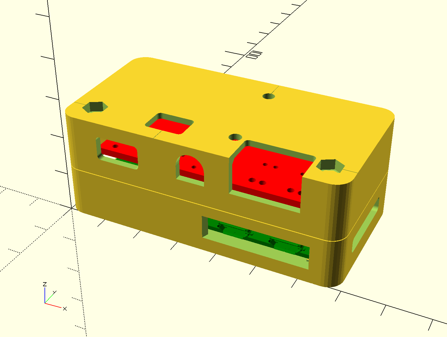
Print with 0.2mm layers and no brim on a standard FDM printer. Materials:
| Quantity | Part |
|---|---|
| 10g | filament PLA or PETG |
| 2 | 6mm M2.5 |
| 2 | 25mm M2.5 |
| 4 | M2.5 Nuts |
| 1 | 2.5mm drill |
| 3 | 8x1mm magnet + glue (optional) |
Assembly instructions:
Step 1:

Use a 2.5mm drill to remove excess material in the screw holes and the spacer.
Step 2:

Fasten the screws.
Step 3:
There is no step three1.
Software
Software for the controller:
Flash the microcontroller with the Arduino Leonardo Bootloader, upload the firmware via the Arduino IDE and you’re set. To flash the bootloader a programmer or another Arduino is required. (This is left as an exercise to the reader).
Software for the Pi Zero:
Link to Github
Caveat: buy a normal Pi Zero, not a W. UART is slightly different on the W and the bluetooth output needs to be redirected to have access to the main UART.
A note on camera compatibility: on the pi runs gphoto2. Every camera that can be controlled by gphoto2, can be triggered by the pi2.
Software for the Smartphone:
Maybe some day...
Links:
…