Perlin noise for 3d-printed parts
08 Oct 2021Recently I spent a bit of time thinking about visually improving non-functional areas of a 3d-printed part. Some generated pattern which could be imprinted on some parts of the object while not creating any issues with geometries that are required for functionality and still being (somewhat) printable.
Disclaimer: I started this inquiry with very little knowledge about 3d stuff (point clouds, meshes and surface reconstruction algorithms) and there may be way better solutions if you’ve got a basic understanding of these topics.
What I ended up with is Perlin noise. That’s a pretty simple way of generating continuous noise patterns on a plane, in a 3d space or any other dimension. In the two-dimensional case you get a pretty nice landscape-like output with hills and valleys (but no caves, no overhangs). That’s one of the many usecases of Perlin noise: generate landscapes in games.
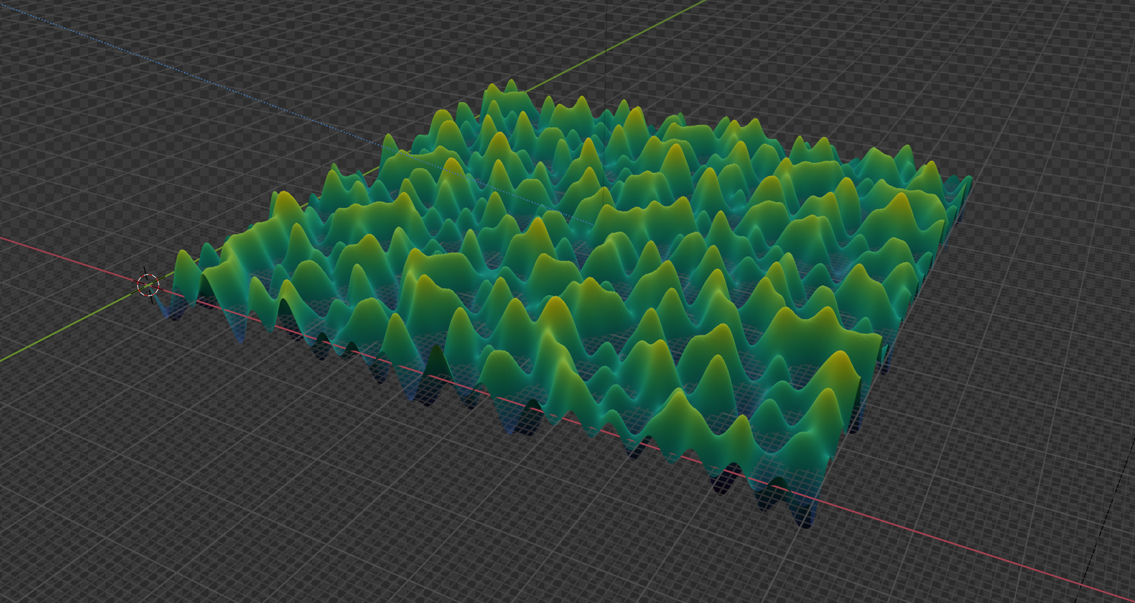
Alternatives to classic or improved Perlin noise are apparently Value noise and Simplex noise, but I just went with the classic flavour. The hard part is understanding the algorithm since there are a lot of explanations of varying quality on differnet algorithms (new and classic). Picking and combining explanations from the posts by Adrian Biagioli and Raouf did work out somehow.
I refactored a bit of code from StackOverflow (as one does) with a slightly different set of gradients. (Python code is available here)
Once you’ve got the algorithm running you get a set of Z values for an XY coordinate grid. How do we make anything 3d-printable from this data? The problem is that STL files are polygon meshes with vertices, edges and faces, but all we’ve got at this point are raw coordinates.
Now we can either generate meshes by directly creating polygons in after computing the noise, or we can continue working with points.
Option A: Meshes
To obtain a mesh, we just connect every set of 4 points to two triangles. The script generates an STL by specifying a filename.
Example:
python3 perlin.py -x 100 -y 100 -z 10 -s 3 --output-stl mesh.stl --surface-only
Option B: Point Clouds
If we continue with points, we basically got a point cloud. Let’s look at that:
Example:
python3 perlin.py -x 100 -y 100 -z 10 -s 3 --output-xyz pointcloud.xyz --surface-only
The most convenient software for visualizing point clouds I could find is MeshLab. I did write the XYZ coordinates of my perlin noise computation to a file, one coordinate tuple per line.
MeshLab can open that via File > Import Mesh.
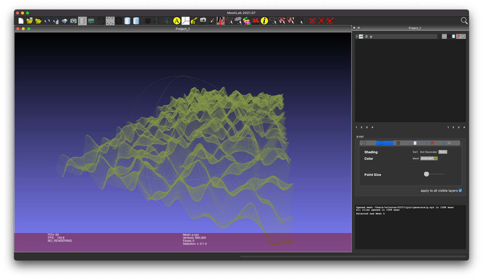
The nice thing about MeshLab is that it comes with a set of common algorithms for point cloud/mesh problems.
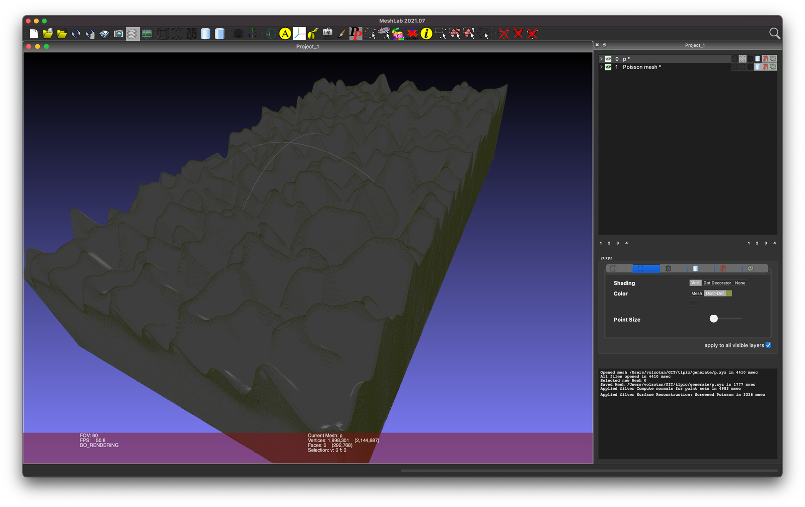
Apparently the correct term for getting from a point cloud to a mesh is “Surface Reconstruction” and the most straightforward way of doing this is a Screened Poisson algorithm. One requirement for that is to have the normals for all points and MeshLab can compute that easily by selecting Filters > Normals, Curvatures and Orientations > Compute normals for point sets.
Now one can just run Filters > Remeshing, Simplification and Reconstruction > Surface Reconstruction: Screened Poisson and hit Apply.
That looks already pretty good! Apparently the algorithm creates a bit of padding at the edges of the point cloud, but that’s not a show stopper. The problem is that our mesh is not actually a body but just a surface.
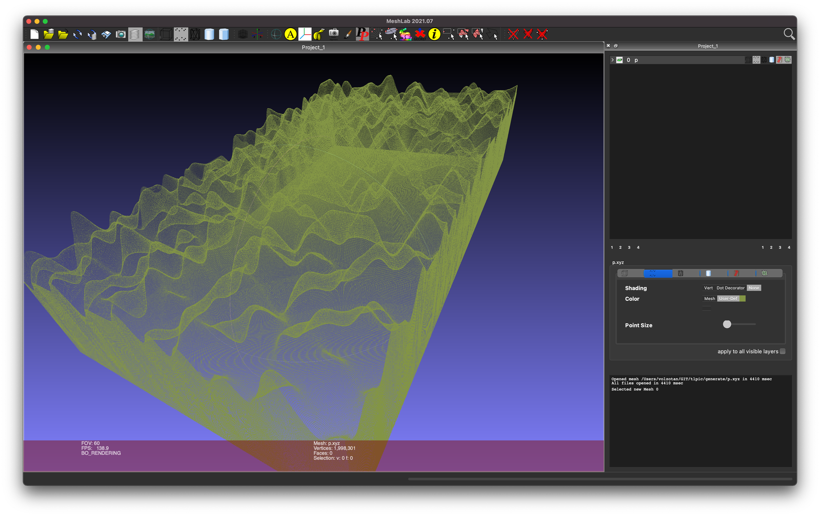
Maybe there is totally conventient way of just extruding this and remeshing or something similar, but I did not find an easy way to do this. What I did instead is change my Perlin noise script to just create point coordinates for “walls” on all four sides and a bottom.
Same steps as before and then hit File > Export Mesh As and select STL.
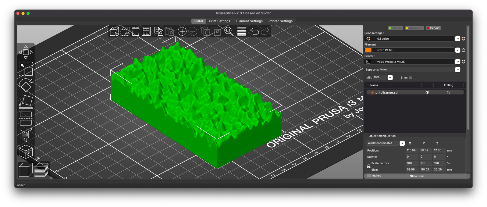
And now we’ve got an STL file that we could just print.
No matter in what way we created an STL file, the following steps are the same:
Result
But how can we use this STL file to modify another STL?
What I did was create another body in my CAD software which encompasses all the non-functional parts of the component. Everything bit of space that this body occupies could be kept or removed depending on the perlin noise output.
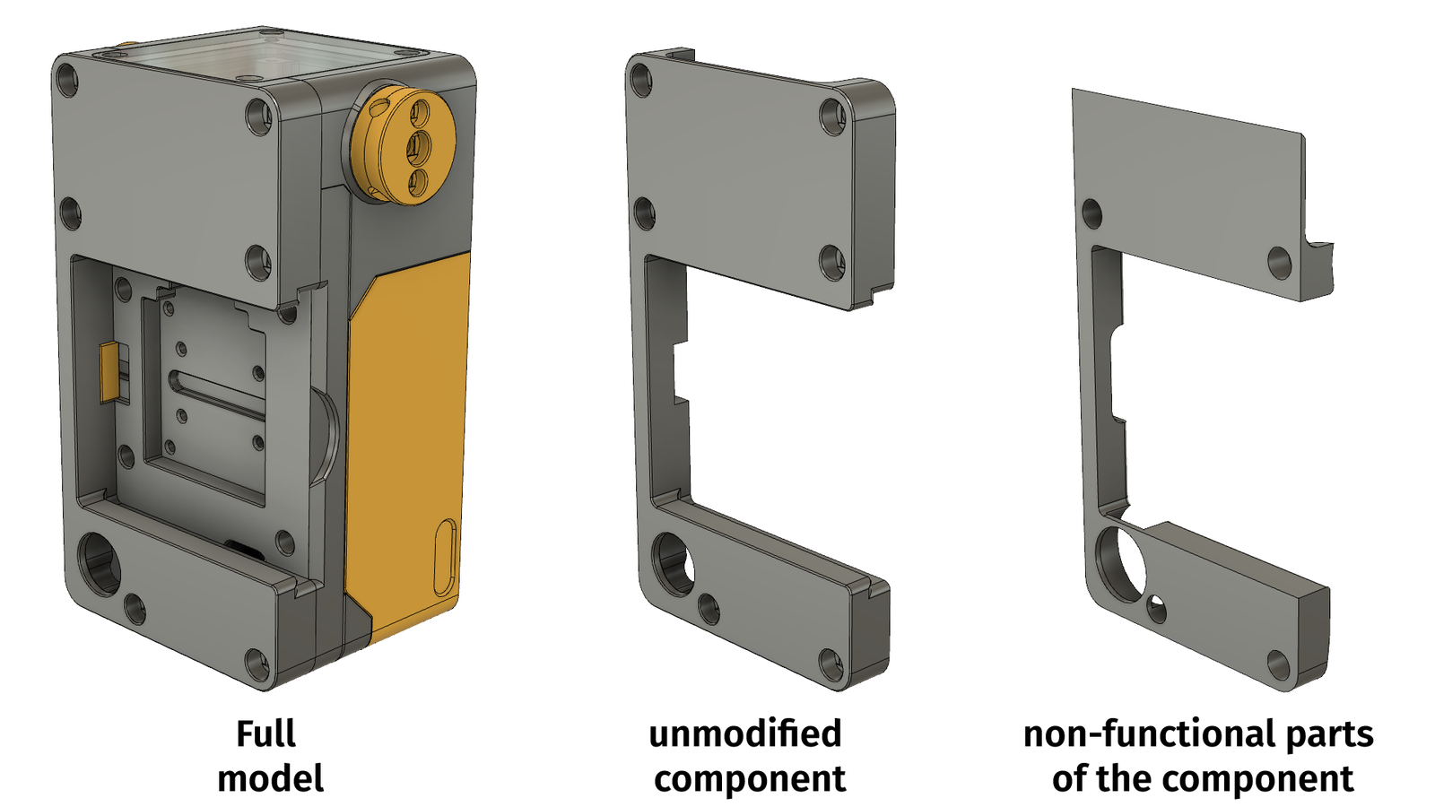
I exported this as an STL as well and combined these meshes with the simplest tool available: boolean operations in OpenScad.
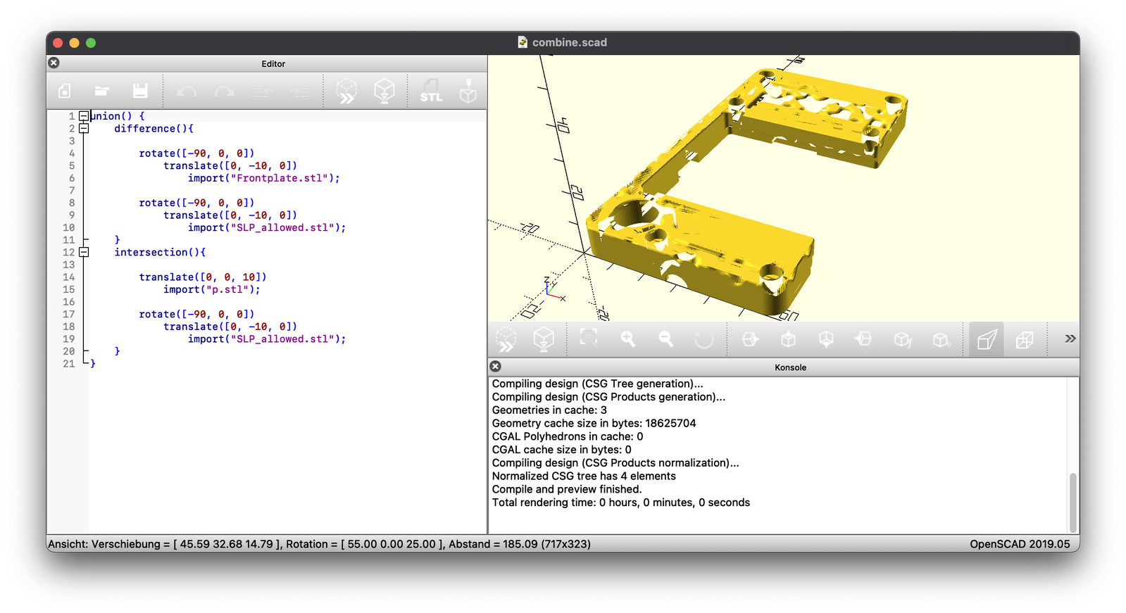
union() {
    difference(){
        import("original_part.stl");
        import("allowed.stl");
    }
    intersection(){
        import("perlin.stl");
        import("allowed.stl");
    }
}
The preview looks pretty awful because OpenScad (or CGAL) is not able to deal well with meshes that have overlapping points/faces. The output is not perfect, but can be repaired with a mesh repair tool or a slicer.
Loading the resulting STL in the slicer looks like this:
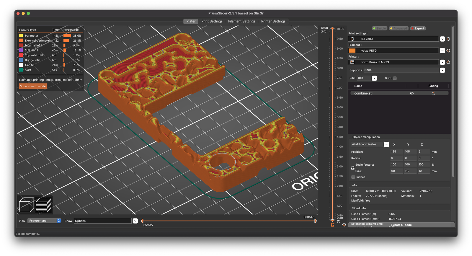
To be able to actually make the perlin noise pattern printable upside down I did cut off all noise values >= 0 (only the valleys, not the hills remain).
So, how does the print look like?
Software?
You can find the script on github.