Making a Hybrid Viewfinder
10 Dec 2022If you have ever used an even moderately fancy analog or digital camera (or a telescope, or a gun sight, …) you are probably familiar with viewfinders. There are different levels of sophistication in relation to the function and engineering complexity of viewfinders, starting with sports viewfinders, more elaborate constructions offering a demagnification (a wider field of view than the human eye), adding indicator lines for framing and even offering overlays for proper focussing (rangefinders). Once you put a digital sensor in a camera, a lot of viewfinders get pretty boring really fast. Why use a viewfinder if you’ve got a display with a live sensor readout? Well, there are still a few advantages (other than pure nostalgia), so viewfinders made their comeback as EVFs or Electronic Viewfinders (a tiny display with some optics to give you the impression of a really large display in front of your eye).
And that’s kind of a good tradeoff. Especially if you’ve got an interchangeable lens camera your EVF is the only sensible option. But Fujifilm did something weird a few years ago. They released the X100, a camera with a fixed lens and something they called a “hybrid viewfinder”. Basically a combination of an optical viewfinder with a digital overlay. Fancy? Fancy! Can we build something similar? Like built our own viewfinder and make it a hybrid one? Sure. Let’s start with the basics:
But before we do that, let me put a tiny disclaimer here: I am not an optics person. I spent most of my rather low-quality physics classes daydreaming and I have very little clue what I am talking about here, take everything with a rather large grain of salt. I’ll add links whenever possible and encourage further reading.
So, step one:
How does a viewfinder work?
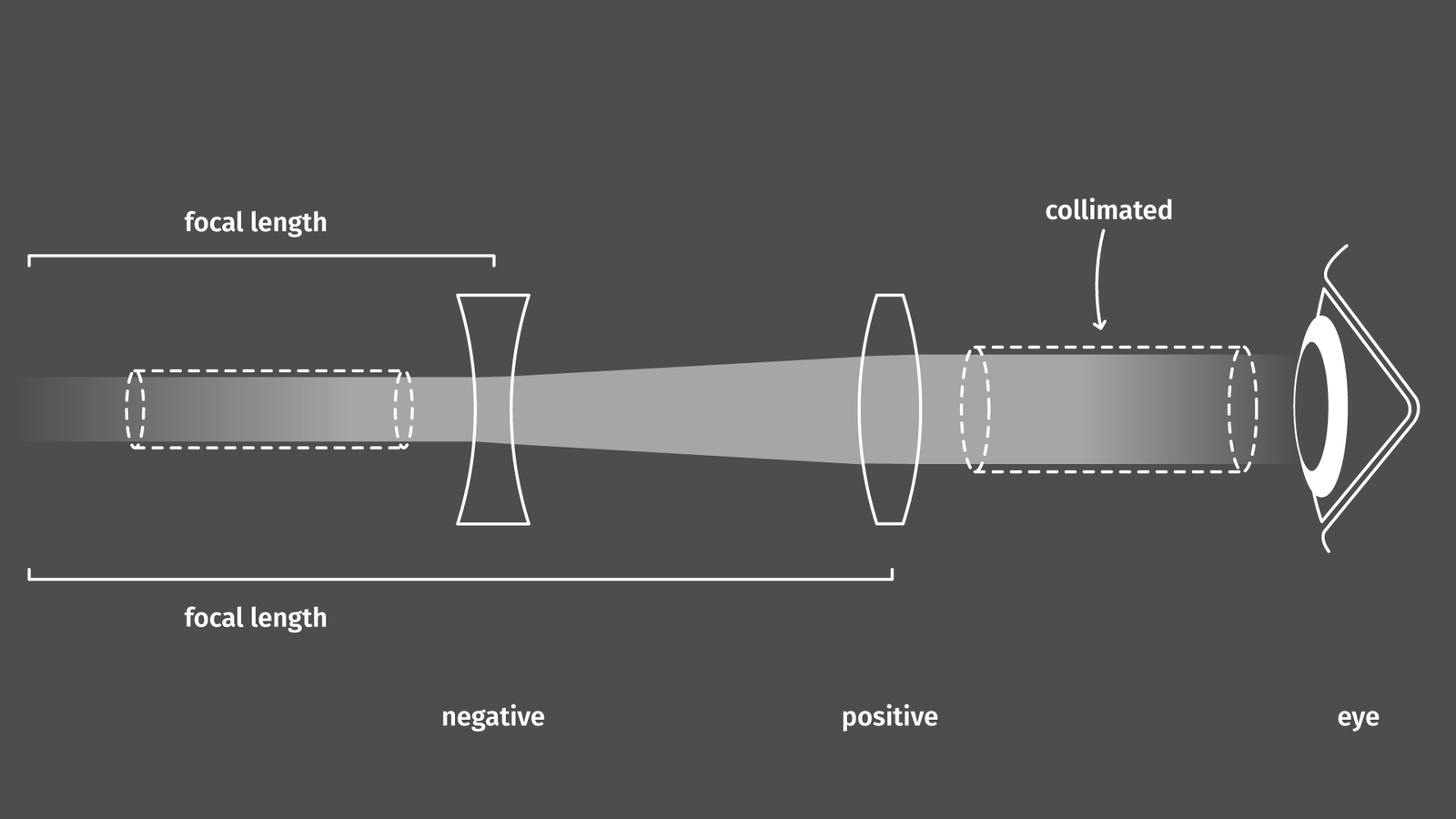
That was a rather complicated question and sometimes there is an abundance of information available on the internet regarding a specific topic. Sometimes there is almost none. Luckily, Rick Oleson did an exhaustive compilation on the history of viewfinders and rangefinders which actually includes ray diagrams explaining how light travels through the optical system of the viewfinder. This was an extremely helpful resource and is one of these excellent examples where a single person is almost the singular authority when it comes to collecting all necessary info regarding a certain topic on their personal internet page (other examples include Redblobgame’s Hexagons or Paul Bourke’s Fisheyes). Anyway, back to the topic: viewfinders. The simplest and best-performing viewfinder concept that is listed in Oleson’s overview (and is still in use today) is the “Reverse Galilean Telescope”. Basically two lenses, one is negative, letting incoming rays diverge (thus demagnifying) and a second positive lens which collimates the rays, making them enter the pupil of the eye in parallel.
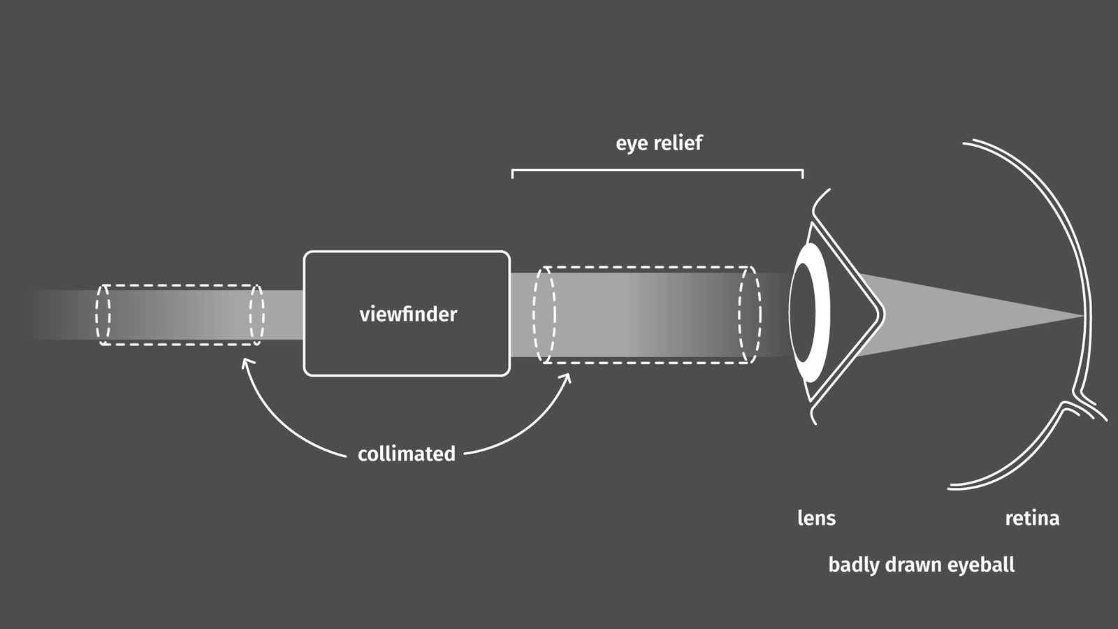
A short excursion on optics: when designing a lens for a camera incoming light needs to be focussed onto a plane, forming an image. This plane can be occupied by film, a sensor, or anything else that can make sense of a focused image. When talking about optics that are for human operation (read: should put light directly into the human eye) exiting light needs to be shaped in a way that the lens of the eye can focus it onto the retina. Thus, most of the stuff that is put in front of our eye, e.g. scope things (riflescope, telescope, …), tries to make light exit in (almost) parallel rays (collimated) at a maximum width of a few millimeters (the size of our pupil) so it can be focussed by a relaxed lens in our eye onto the retina. If the rays are not parallel, we need to compress the lens in our eye (focus close instead of on an infinitely far away object light the horizon).
So, back to the reverse galilean: A Galilean telescope takes light from an infinitely far away object, e.g. the moon or a star (so light that basically hits in parallel rays) and expands the beam (magnifies it) and lets it exit in parallel again, ready for processing by the human vision apparatus. The nice thing about a Galilean in comparison to a Keplerian telescope is that the light is not going through a focal point within the tube of the telescope before it is collimated again which would result in a flipped image. Not a big issue when the light would hit a sensor, but kinda annoying for our brain. So, we know how a Galilean telescope works, and if we want to have a broader field of view instead of a narrower one, we just need to flip the optics, thus a reversed galilean viewfinder. Cool!
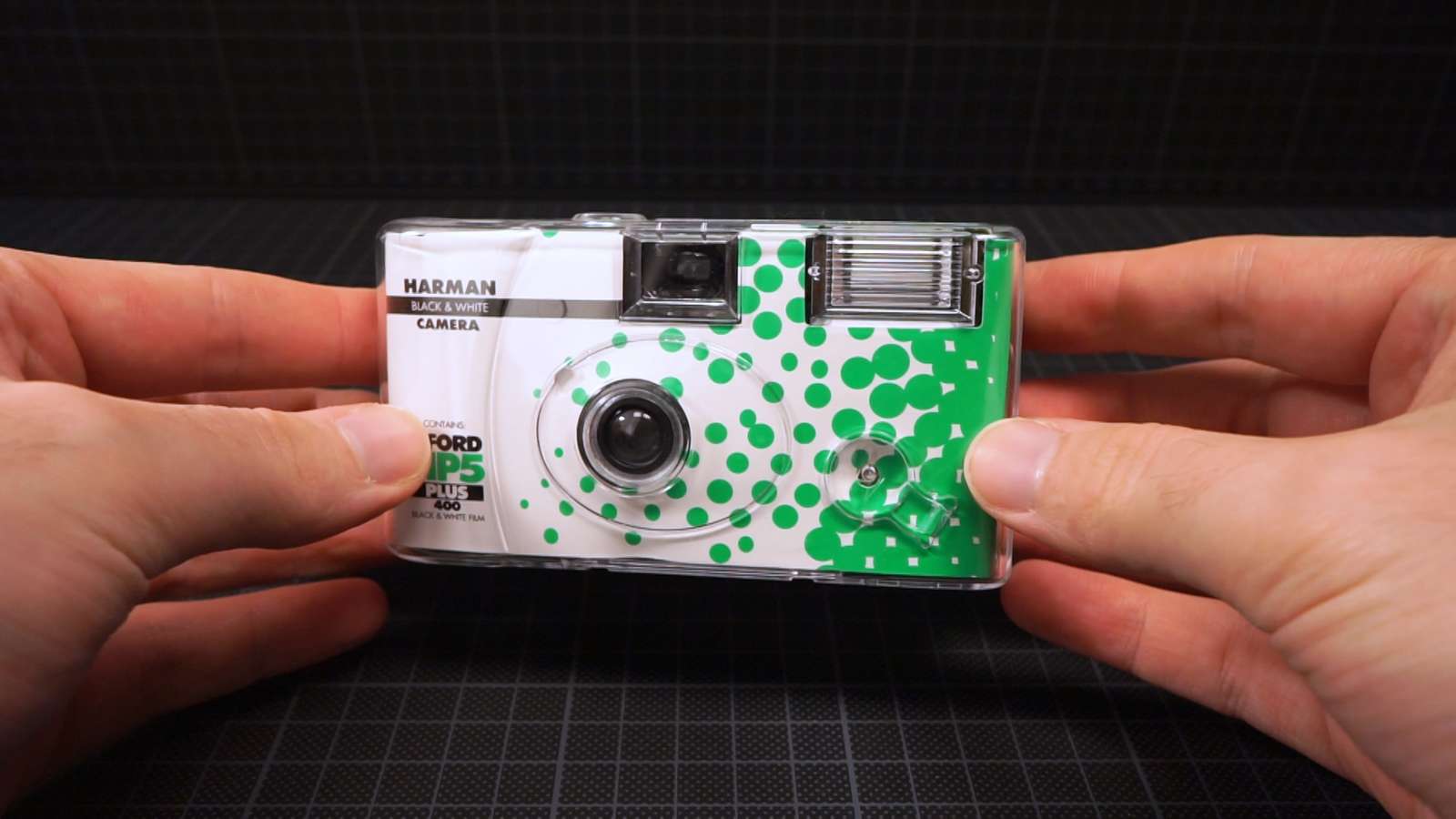
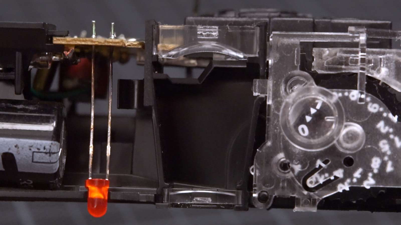
Most viewfinders that we can purchase today are actually reverse galileans. The viewfinders in cheap single-use film cameras for example are just two acrylic plastic lenses, one negative, one positive, forming a reverse galilean.
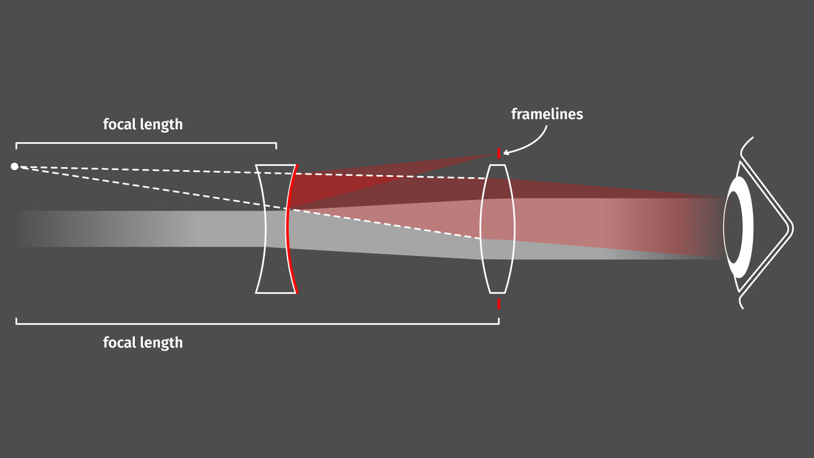
But, there is an issue with reverse galilean designs: sometimes it would be really cool to add something to the image in the viewfinder. This could be framelines for cameras or crosshairs in a riflescope. Because the focal point of the negative lens lies in front of the viewfinder, the only place in the optical system where you could place something that would be in focus is a few centimeters in front of the viewfinder. Not very practical. There are two ways how we can deal with that. One option is to magically extend the optical path to add framelines placed at the appropriate distance without obstructing the front view of the viewfinder (that’s what a lot of rangefinder designs did and what we will do) or the Albada-style viewfinder: A dutchman named van Albada came up with the idea of using a semi-translucent mirror coating on the interior surface of the negative lens to reflect a hidden image from inside the viewfinder into the optical path, neatly hiding the necessary image of framelines within the viewfinder housing.
That’s the design of nearly all fancy and expensive modern viewfinders you can buy to slide them in the hotshoe of your camera (example: Ricoh Viewfinder).
How can we build a viewfinder?
So, which lenses do we need to build a reverse galilean viewfinder and where do we get them? Basically whenever choosing lenses we got two options: lenses with one uncurved surface and one curved surface (called a plano-concave/convex) or lenses that have curvatures on both sides (bi-concave/convex).
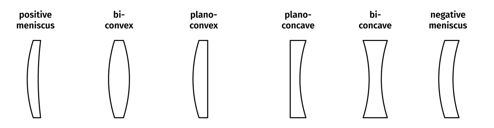
In addition to that there are surfaces that have a spherical curvature (easy to compute, easy to manufacture) and aspherical curvatures which are described by a polygon (harder to compute, harder to manufacture). We go easy and go with a plano-concave and a plano-convex spherical lens, that’s cheaper and easier).
The simplified equations for a galilean viewfinder are nicely summarized in a blog post by Panomicron. In general, when doing optical design people start with thin lenses (assuming that each lens is an infinitely thin idealized surface) and paraxial equations (assuming that the refraction of light obeys a very simple formula close to the optical axis). Usually, that’s good for the rough design. Since we don’t want to go down the rabbit hole on how to make our own custom lenses, we stick to off-the-shelf parts we can buy from a lens manufacturer. It may even be clever to go with plastic lenses (made from PMMA, also known as Plexiglas/acrylic glass) since they perform slightly worse but are way cheaper, but I couldn’t find a vendor for those that has a wide range of optics to choose from. When sticking to glass lenses, there is basically just Edmund Optics with a sufficient catalog. By picking something from the catalog, design options are a lot easier as well, because once we decided on the two required lenses, we just need to find the right distance between them (less options, less variables to optimize for).
In this case, I decided for a design that is as simple as possible. The negative (plano-concave) lens is a -30mm lens with 20mm diameter (part number 45-021). The positive (plano-convex) lens is a +60mm lens with 20mm diameter (part number 32-963).
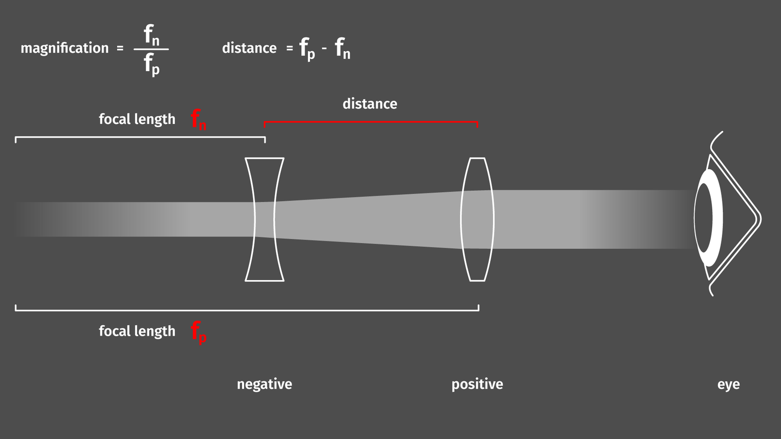
Using the paraxial thin-lens approximation, the distance would be -30+60=30mm, that’s important for the next step. The ratio of focal lengths results in a magnification ratio of 0.5, that should be sufficient for lenses not wider than 25mm. The anti-reflection coating in this case is some plain Magnesium Fluoride (MgF2) coating, which apparently is good enough for visible wavelengths. Since I don’t want to shoot some high-powered laser beams through these lenses I assume that’s more than sufficient.
But how do we get the precise distance between both elements? We can compute that using the back and front focal distances from the datasheets that Edmund is publishing for their lenses. Or we can just crunch the numbers with software. I did this in this case with Zemax OpticStudio, adding the lenses from the built-in lens catalog. Usually when designing things the convention dictates that light travels from left to right through the optical system but for eyepieces it is apparently not uncommon to change that. Defining a light source with parallel rays about the size of the human eye’s pupil and shooting the light into the viewfinder (that’s what I did here). So imagine the eye is placed on the left side looking at a far-away object to the right.
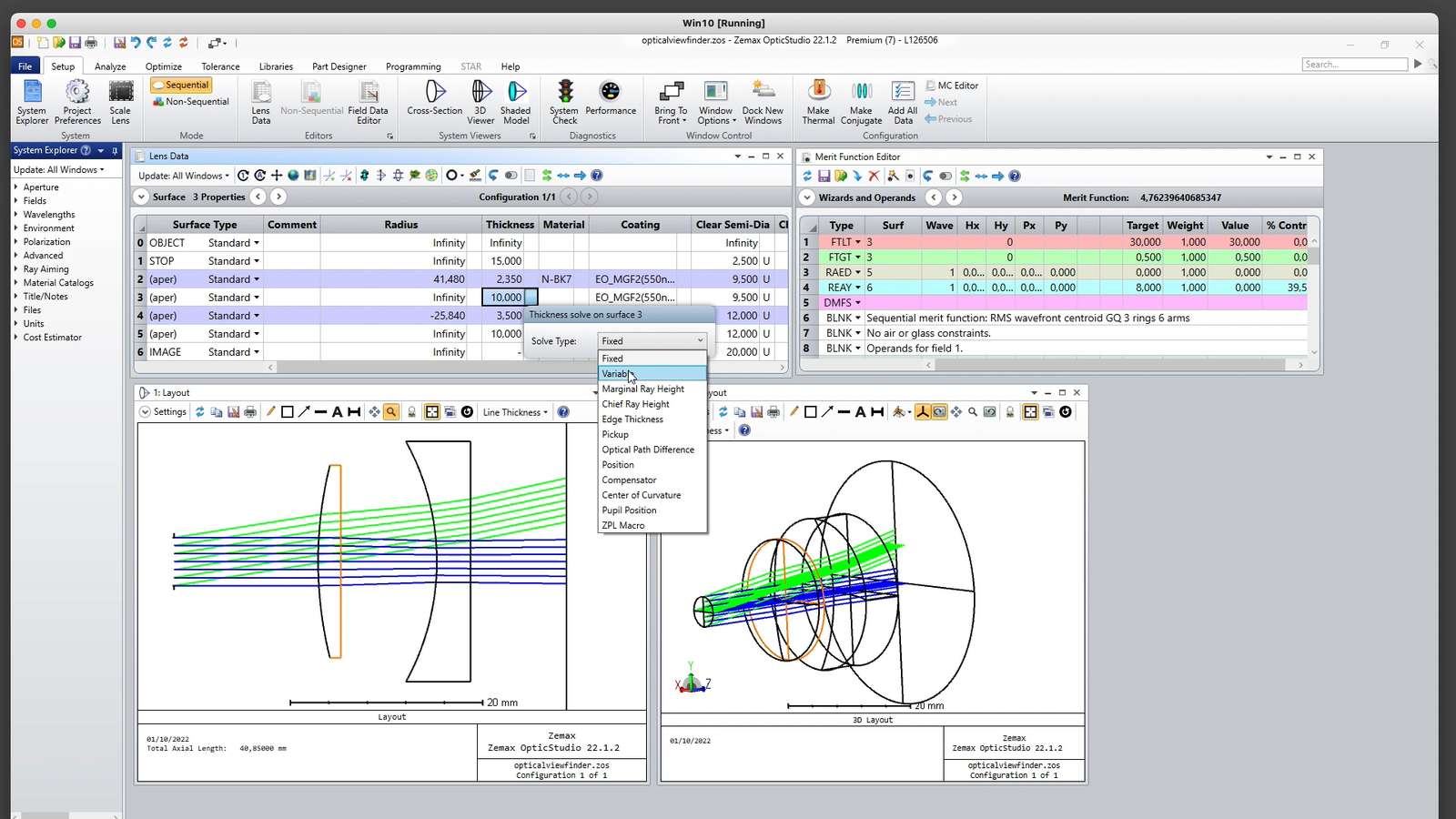
When letting OpticStudio optimize the distance between both lenses with the goal of creating output rays as parallel as possible, we get a distance of 27.964mm. Then we just need to print an enclosure and everything just works (usually not, but in this case it did).
Make it hybrid!
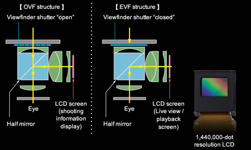
Next step: add an overlay. So, how can we add an overlay? Apparently, when doing a course on optics, there is some chapter about the swiss knife of optical engineering, the magical tool that is also known as a prism. Prisms can be used and abused for numerous purposes from micro-adjusting angles and distances, to flipping images along different axes, refracting light, and … in our case: beamsplitting. The idea is to use a prism at a 45-degree angle and coat the surface with just a very thin layer of reflective metal. By just adding enough metal to get the surface to 50 percent reflection we can create a beam splitter. Half of the light travels unobstructed through the prism (almost like a window) half of the light gets reflected at a 90-degree angle. If that sounds familiar: that’s exactly how teleprompters work or the famous Pepper’s Ghost illusion. When we look at Fujifilm’s long gone product page in the wayback machine we spot exactly that for the X100’s hybrid viewfinder!
Thanks marketing people! I am not trying to be sarcastic here, the old product page has a lot of surprisingly in-depth info about the X100’s development process, I do greatly appreciate this type of product stories! There is even a diagram showing the type of lenses:
We can save ourselves a bit of hassle and just put two prisms together along their angled faces to get a beamsplitter cube. That’s slightly more convenient for optical calculations and easier to align when we actually assemble our viewfinder. The issue is that beamsplitter cubes are annoyingly expensive when purchased at Edmund Optics, but unlike the precision lenses, it is quite easy to get a cheap one from China via Aliexpress (Link may be dead in the future but at the time of writing a 20x20mm beamsplitter cube was about 23 Euro on Aliexpress). When we add a clear 20mm cube to our optical system in OpticStudio distances change slightly but since we got about 30mm of distance in between the lenses we can easily fit our 20mm cube in the gap.
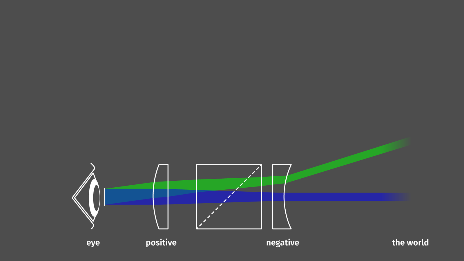
Now the only thing we still miss is a display. But let’s talk about our optical system again for a moment: keep in mind how the galilean viewfinder works. Light enters in parallel rays and exits in parallel rays to be focussed by our eye on our retina. When using the viewfinder the eye focuses on infinity to get a sharp image on the retina. When we want to overlay an image from a display, the light emitted by the display needs to enter the light in parallel as well since our eye can’t focus on the display up close and an infinitely far away object at the same time. The optical path from display to eye involves just the beamsplitter and the positive lens close to the eye, not the negative lens towards the front. The positive lens has a focal point of about 80mm in front of the lens. So if we place a point light source exactly at the focal point the light rays exiting the lens would be parallel (Basically a magnifying lens). Can we do that? Sure! Probably there is a clever way to model both optical paths in a single system with OpticStudio, but for me, it was way simpler to model them in two different projects.
Viewfinder only with the beamsplitter as a 20mm glass cube:
Display overlay only with positive lens looking at the display through the reflection created by the beamsplitter:
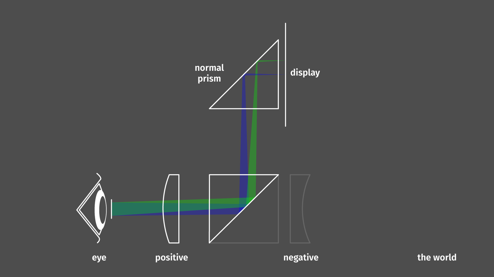
As a display, I am not using a dedicated small high-resolution display similar to the Fujifilm X100 but a good old smartphone display, so we need a second prism to reflect the light by 90 degrees again.
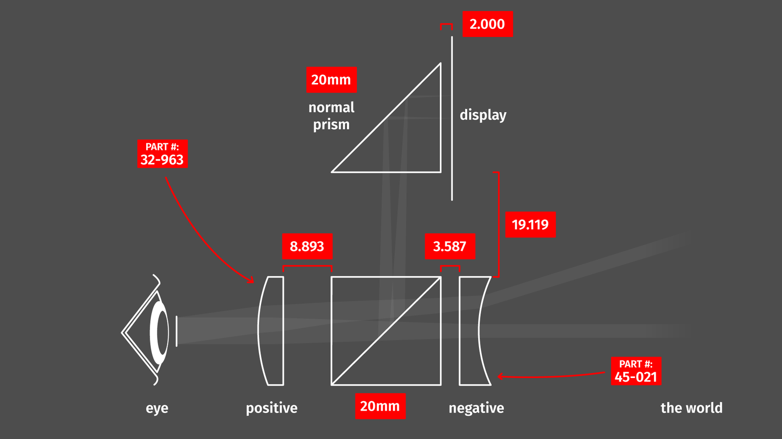
OpticStudio can now compute the four distances (red in the image above) between all elements of the optical system so the light enters and exits as collimated as possible.
One thing that’s a bit tricky is getting the materials right. Every type of optical glass has a slightly different refraction value, so it bends light a tiny bit more or less strongly. For the lenses we know the exact type of glass and all dimensions thanks to the built-in lens catalog (or the Edmund Optics datasheets) so OpticStudio is handling this for us. For the prisms, we don’t because that’s cheap stuff from AliExpress. I assume it is H-K9L, a local chinese equivalent to Schott’s N-BK7 glass, probably the most common material for general-purpose optical stuff. So I am using the settings for N-BK7 and hope that the error is negligible.
Once we’ve got the exact distances, we’re done with the optical design part.
Make it!
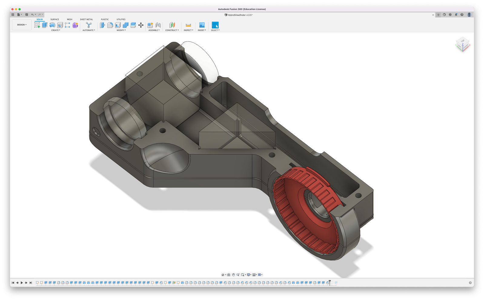
When designing a 3d-printable enclosure for the optical components I don’t care much about micrometer adjustability of the components. If distances and angles are a bit off (introducing aberrations and making it slightly less sharp in the corners) that’s simply something we need to live with. The lenses are just a press-fit since I absolutely want to avoid using glue (just a bit of superglue already creates enough vapor to permanently blur any glass surface in the vicinity).
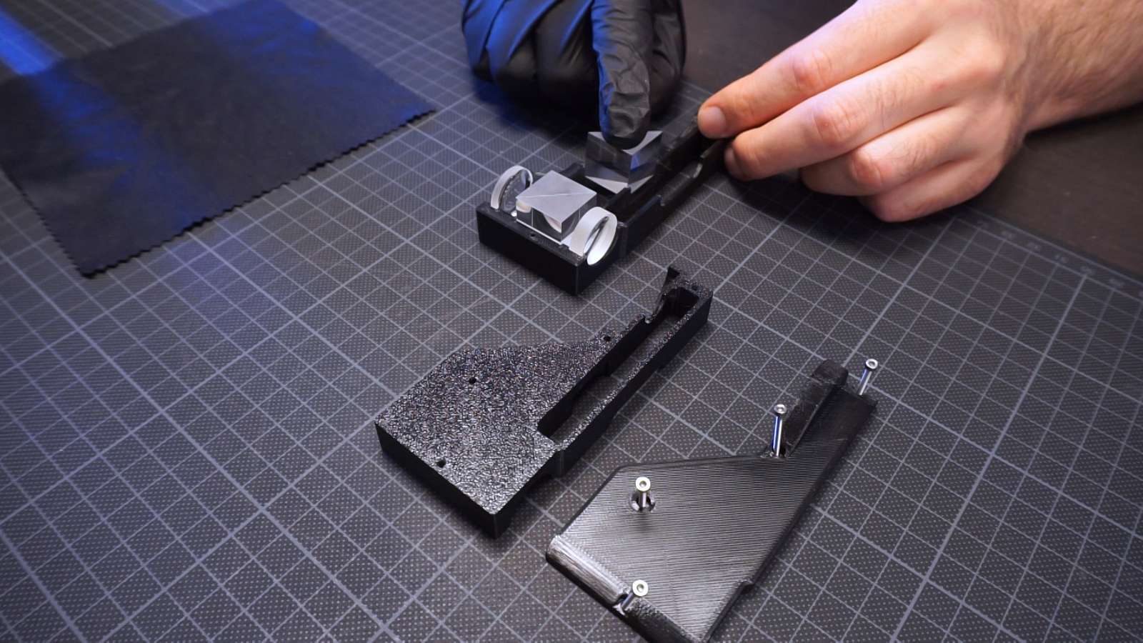
I am printing these parts on a regular 3d printer with 0.15mm layer height and black PETG plastic. For a perfect fit, a bit of sanding is necessary to create smooth top surfaces. The material creates a few tiny strands of plastic while printing especially if it’s a bit older and had the chance to absorb water from the air. A second with a heat gun gets rid of those.
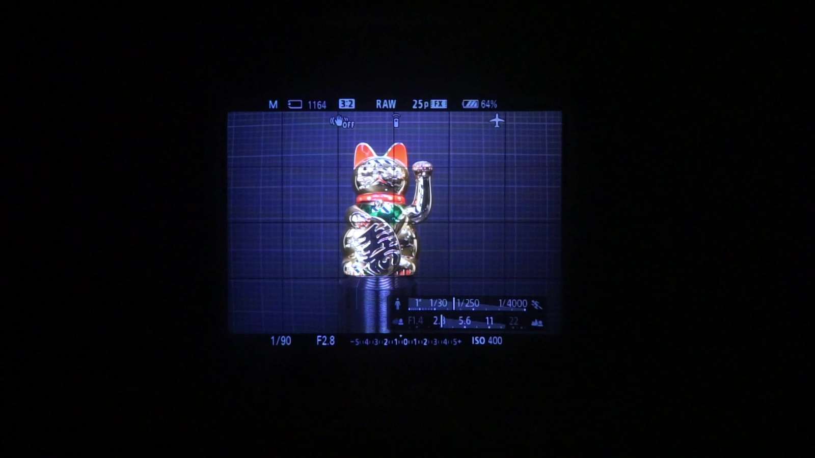
The viewfinder assembly fits on a smartphone (an old LG G6 Android phone in this case):
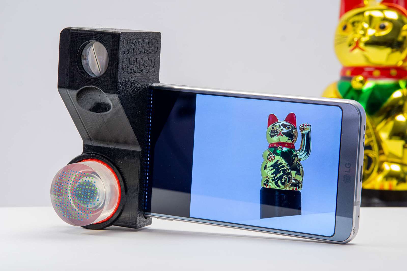
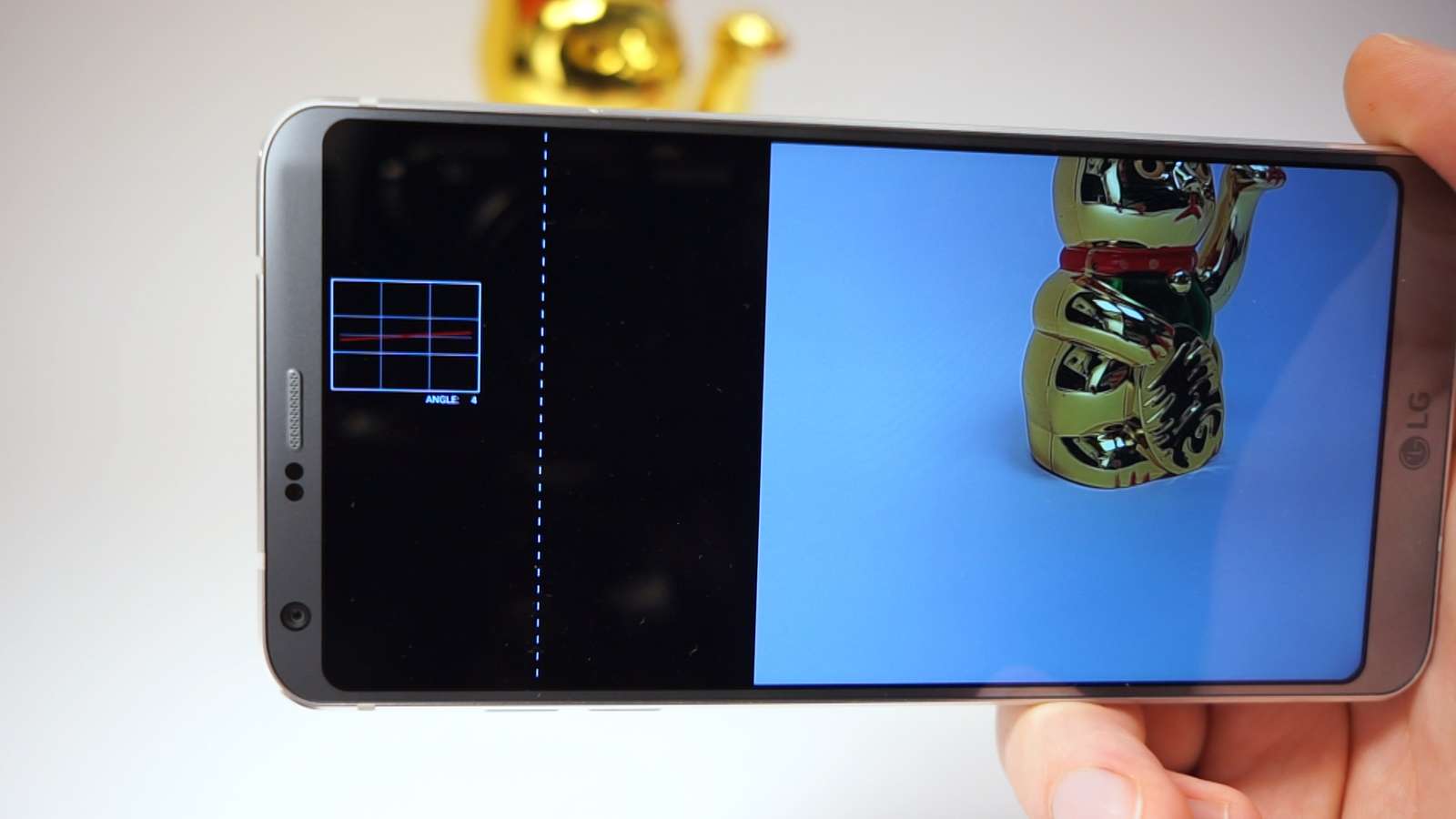
As a demo, I wrote an Android app that makes use of the small display area that gets picked up by the hybrid viewfinder. I can display some additional info or spirit level, etc.
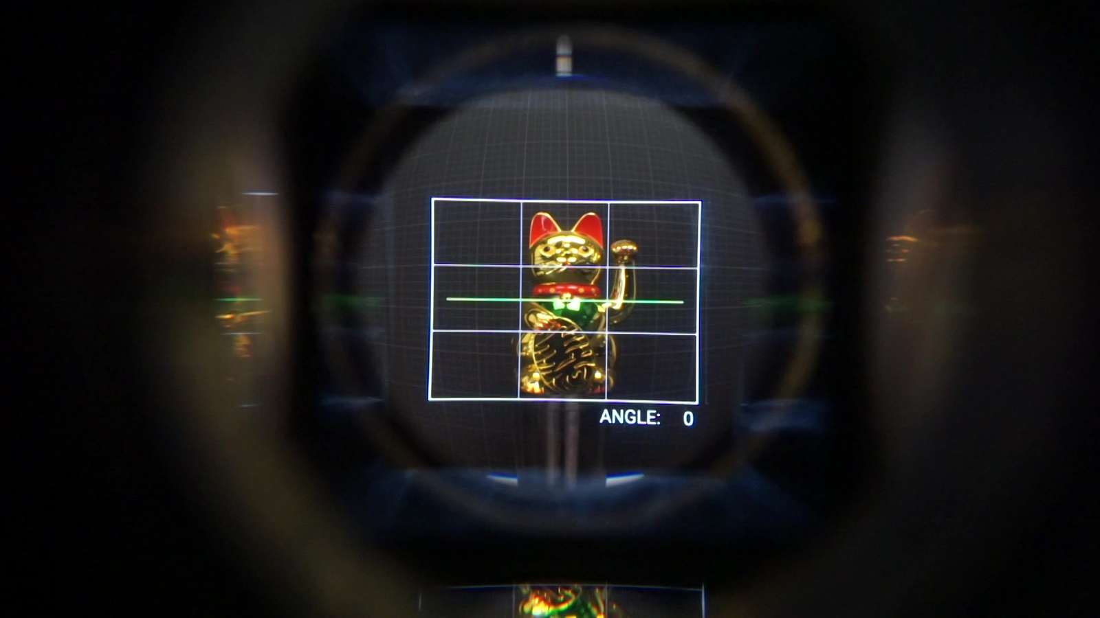
So, how does it look?
Now we see that the magnification ratio of 0.5 makes sense. When looking through the finder the 50mm focal length of the human eye becomes 25mm and that matches the 24mm lens of the phone somewhat.
Problems:
The optical path of the light emitted by the display involves only the positive lens and the prisms, nothing else. The X100 is using another negative lens and a doublet. So our overlay has a lot more distortion and chromatic aberration compared to the X100 because we don’t have any additional lenses to cancel out these errors.
Another issue is that the pixel density of the smartphone is high but not crazy high. I am using the LG G6 here with about 560 PPI and that’s totally okay for your bare eye. But the lenses and prisms are rather small and the actual size of the segment of the display that is overlaid is just 370 by 370 pixels. For comparison, the electronic viewfinder of my (rather old) camera has three and a half times more pixels. That makes the overlay a bit blocky and pixelated.
Outro:
If you want to build something similar, I linked the CAD files and OpticStudio files below. Although, if you own/have access to OpticStudio there is a high chance that you know how all of that stuff works way better than I do and you should not be reading this article.
Files:
Sources:
- Rick Oleson’s Looking Foward viewfinder page
- Applied Photographic Optics by Sidney F. Ray: an overview about all things optic for photographic purposes. Can be borrowed digitally on archive.org
- Photography Its Materials and Processes a slightly dated book that has entered the public domain and is available on archive.org
- Panomicron’s blog post about his build of a reverse galilean viewfinder
- The Camera Wiki and it’s page about viewfinders
Related things:
- Scavenging the plastic lenses from a Canon Owl’s camera body for a 3d-printed standalone viewfinder: the Metro Case viewfinder
- Repurposing wide-angle lens converter for smartphones or point-and-shoot cameras as viewfinders for 3d-printed cameras: the Goodman Scuda
- DIY viewfinder with off-the-shelf lenses for home-built cameras: the Panomicron Oxygen
Fine print:
This post and all images/videos are licensed under CC BY.
(If not indicated otherwise. CC images/videos published by other people with different licenses are labelled as such. Public domain images are not labelled.)
You are free to Share — copy and redistribute the material in any medium or format and Adapt — remix, transform, and build upon the material for any purpose, even commercially. But you need to take care of Attribution — You must give appropriate credit, provide a link to the license, and indicate if changes were made.
See the FAQ for more info.