LensLeech
Short version (abstract from the paper):
Cameras provide a vast amount of information at high rates and are part of many specialized or general-purpose devices. This versatility makes them suitable for many interaction scenarios, yet they are constrained by geometry and require objects to keep a minimum distance for focusing.
We present the LensLeech, a soft silicone cylinder that can be placed directly on or above lenses. The clear body itself acts as a lens to focus a marker pattern from its surface into the camera it sits on. This allows us to detect rotation, translation, and deformation-based gestures such as pressing or squeezing the soft silicone.
We discuss design requirements, describe fabrication processes, and report on the limitations of such on-lens widgets.
To demonstrate the versatility of LensLeeches, we built prototypes to show application examples for wearable cameras, smartphones, and interchangeable-lens cameras, extending existing devices by providing both optical input and output for new functionality.
PDF | YouTube Video | GitHub Repository
Preamble: This (both video and post) was rather hard to write, because of a simple question: who is the reader? What kind of detail is revelant to you? Shall I be succint and share a high-level concept, appealing to a larger audience? Be thorough and tell the whole story to the (very) small circle of people who might plan to do something similar and will appreciate details? Try something in between and fail both groups? Anyway, let’s try something in between:
Long version:
The problem
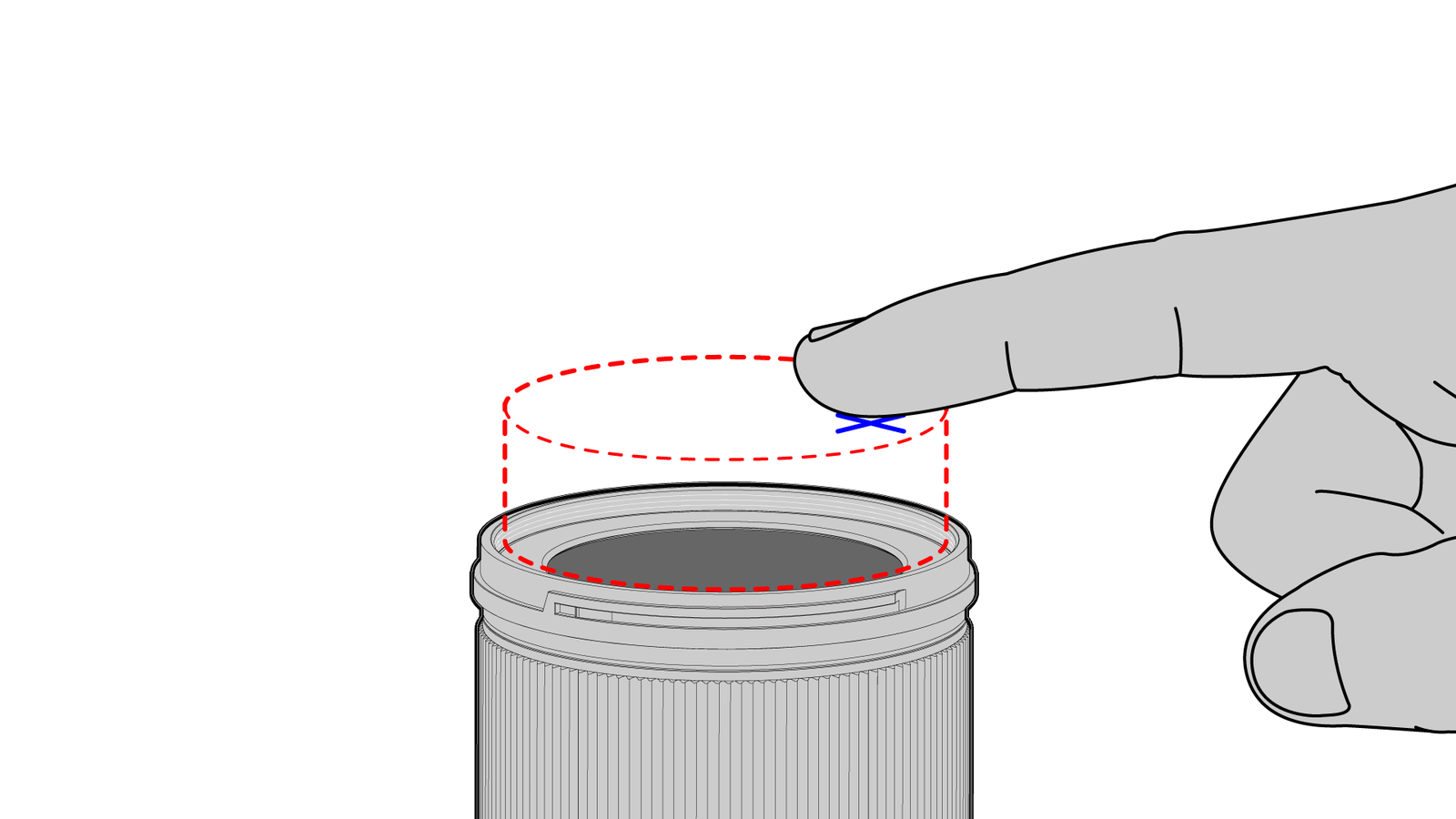
Have you ever felt the urge to touch a lens like a button or a touchscreen? If the answer is yes, this might be a thing for you.
Cameras are pretty crazy little machines. A cheap image sensor might cost about a dollar and has more than 5 million tiny light detectors plus readout circuits and basic signal processing. That’s a lot but still, if you want to use it in a camera, you need to add half a dozen buttons and a screen. Each of button has a mechanical spring, a contact, and a cable, you need to read the voltage, filter the signal, trigger a software interrupt, and so on. That stuff is absurdly large and clunky compared to the semiconductor structures on the sensor itself.
A while ago I asked myself the question: how would a camera need to work that has no physical buttons? No dials, no knobs, no touchscreens? And how good (or bad) would that actually be?
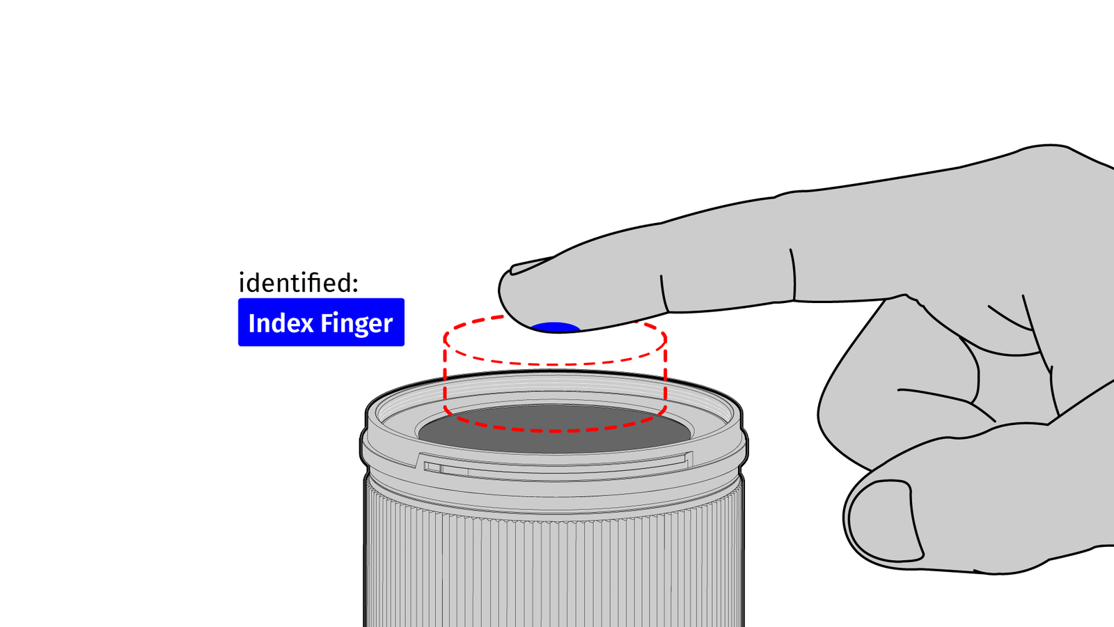
So, I tried to make one and my first attempt was basically a camera with a single button. It – kinda – worked but had a few shortcomings of course and I cheated a bit. One of the basic ideas was that the single button is checking your fingerprints so you can trigger multiple actions depending on which finger you use. But that was not really a solution and in the end, I was still stuck with the problem: how can I process enough user input for something like a camera to work comfortably without having to rely on electrical buttons or capacitive touchscreens?
So, how do we get information into the camera? When dealing with computers or other digital devices – no matter if large or small – there are a few interaction techniques that go beyond the usual concepts like windows, icons, menus, and pointers.
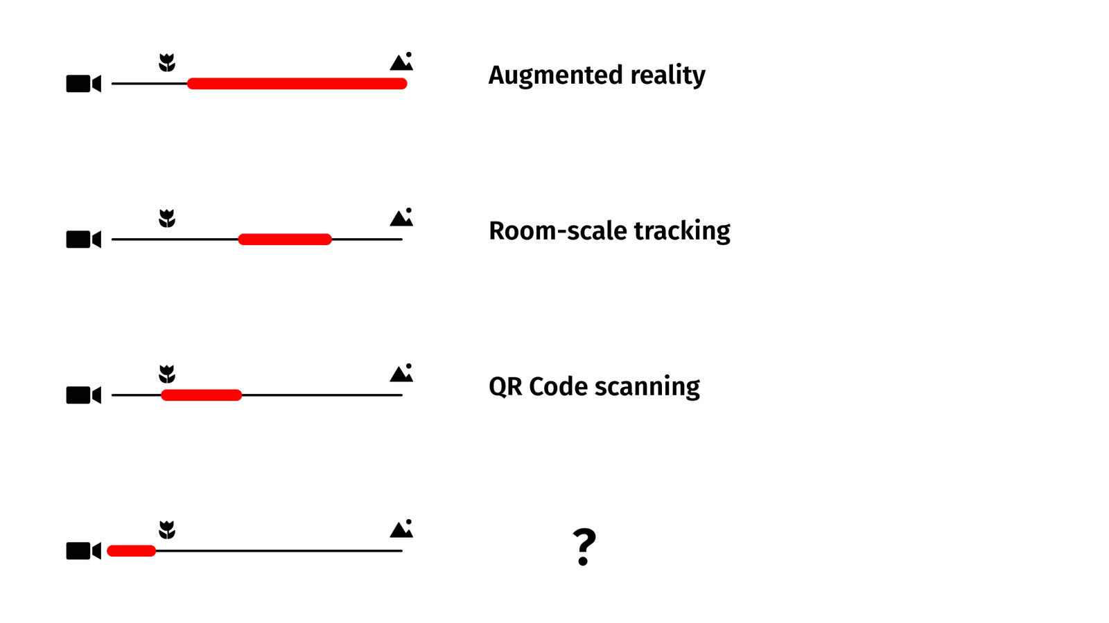
Some of these techniques are based on input from cameras. If they do they usually happen within a certain distance.
Augmented reality overlays can add names to mountains on the horizon or images to pages of a book. When cameras are tracking your position for VR games, the distance may be a meter or two between you and the tracking hardware. When you are scanning a QR code you are holding your phone somewhere at a distance of 20 centimeters to a meter or so. But you never do something directly on your camera. And there is a reason for that: minimal focal distance.
The point is, for most applications, there is a sweet spot between the necessary physical distance, the desired amount of context, and the minimal amount of details of the object you are pointing your camera at. But there is a second reason and that’s minimal focal distance. Unless you are using special optics, you simply can’t get closer to the camera or it is not able to focus anymore and there is only so much data you can extract from a blurred image.
But it would be pretty nice if we could have some way of getting input directly on or above a camera lens.
Related Work:
Okay, chances are high that I am not the first person who came up with this idea. Let’s look at some academic papers from the field of human-computer interaction (and by some, I mean two because there are only two, at least to the best of my knowledge):
First, there is LensGesture (SciHub) by Xiang Xiao et al. The idea is that your finger is sliding over a smartphone camera and by feeding the image data into a neural network you can detect a few simple gestures.
The other paper is CamTrackPoint (SciHub) by Wataru Yamada et al. They are using a 3d-printed smartphone case with an integrated black ring on springs. By placing the finger on the ring and moving it, some light is still going through the tissue of the finger while you can see the occlusion of the ring on the camera. That’s a bit more reliable and easier when it comes to image processing.
Both of these concepts make use of blurry image data and your naked finger. That has a certain advantage because you don’t need any additional stuff, except a modified phone case for one of the papers.
But, at least for the gestures, there is the usual problem: “Your data is shit, just throw AI at it.”
But let’s see if we can improve on that. Basically, we need to know more about the finger so we can use this as an input to interaction techniques. Maybe the exact position, maybe the pressure the finger is putting on an object or the lens, maybe some additional stuff. But we can’t get that from thin air, the finger needs to interact with something and it’s better not the lens! Both papers did work with smartphones because smartphone lenses are covered by hardened sapphire or tempered glass. But not all cameras are similarly sturdy.
The Solution
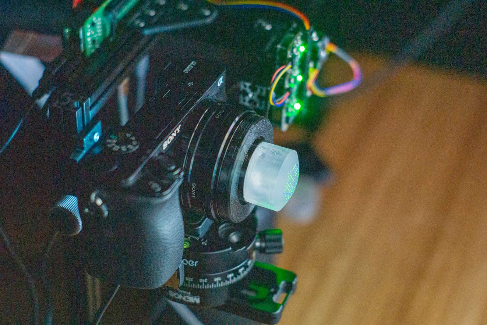
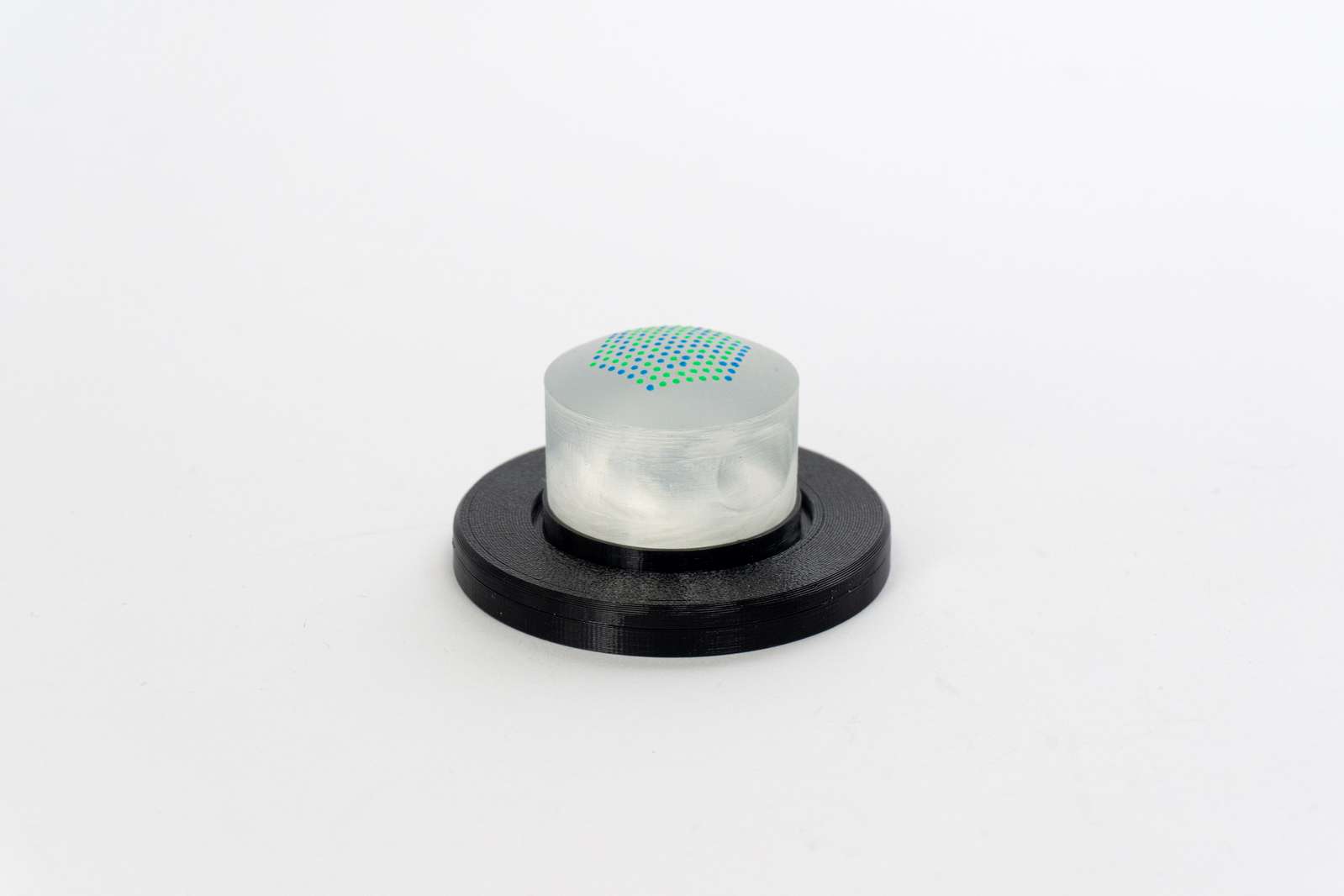
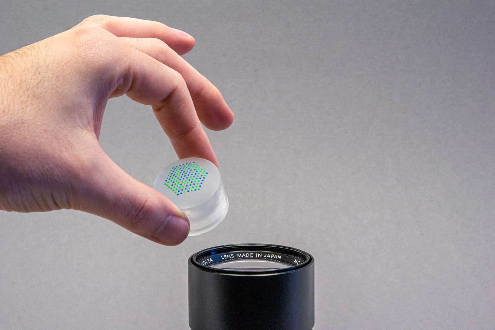
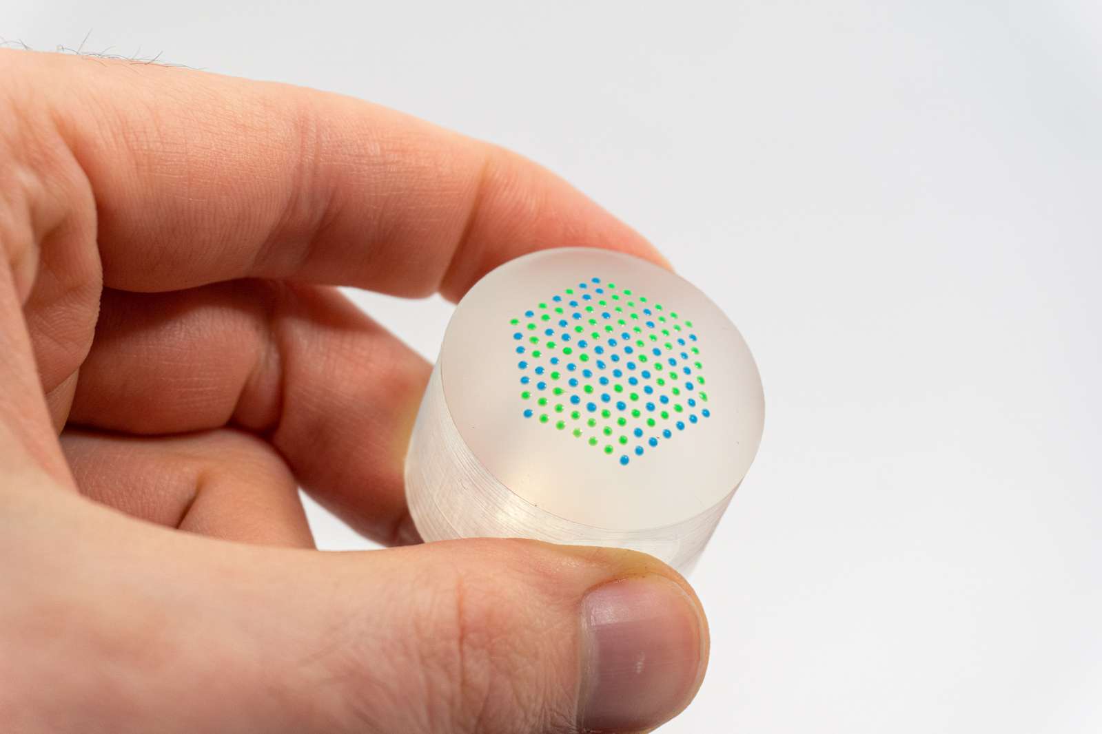
Let’s skip a few mental steps and a lot of failed experiments here and allow me to introduce the blob:
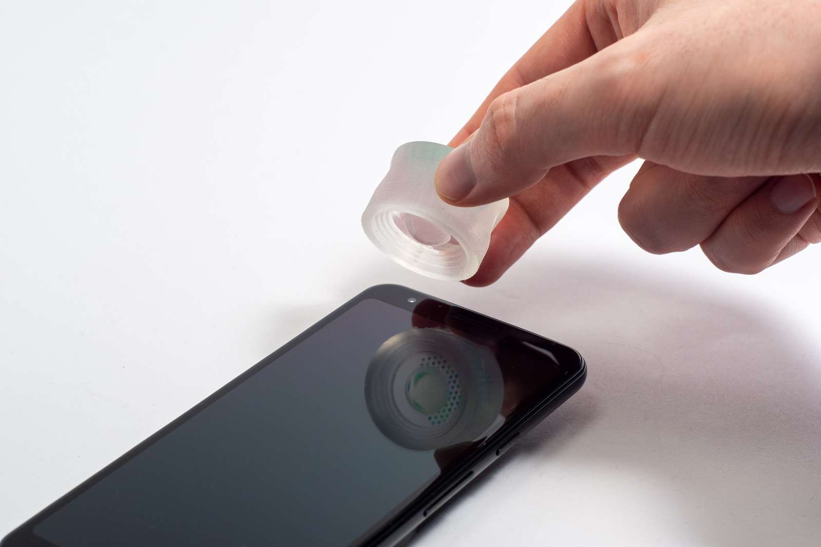
The blob is a, well, a blob. It’s made from soft silicone. It doesn’t scratch the glass surface it sits on and it’s considerably less greasy than the average human fingertip. In addition to its remarkable property of being soft and squishy, it’s also clear.
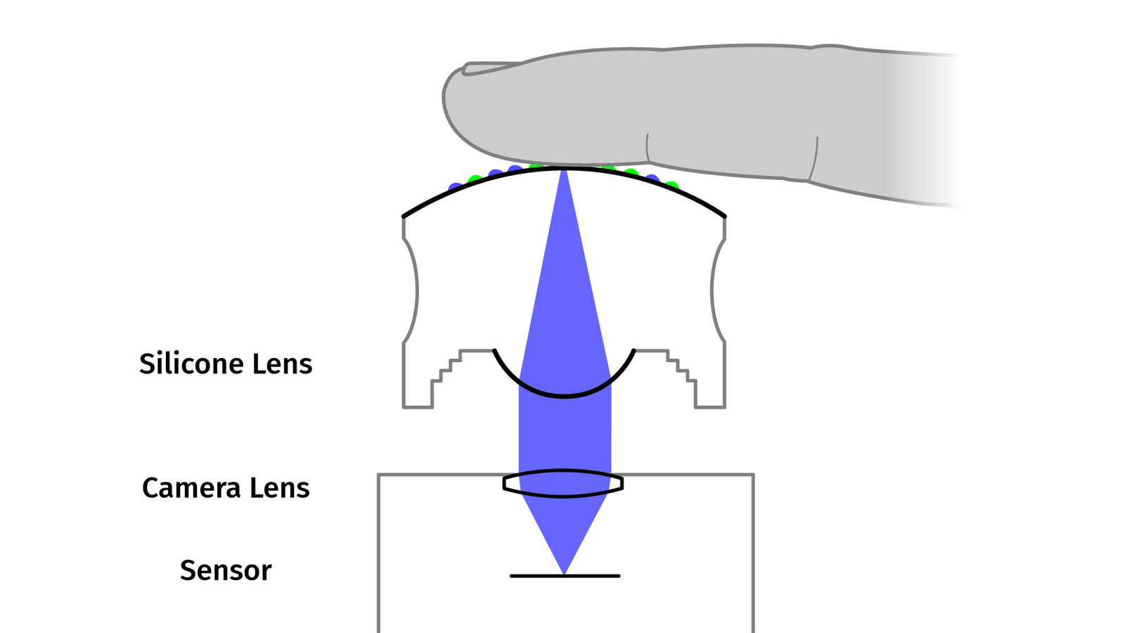
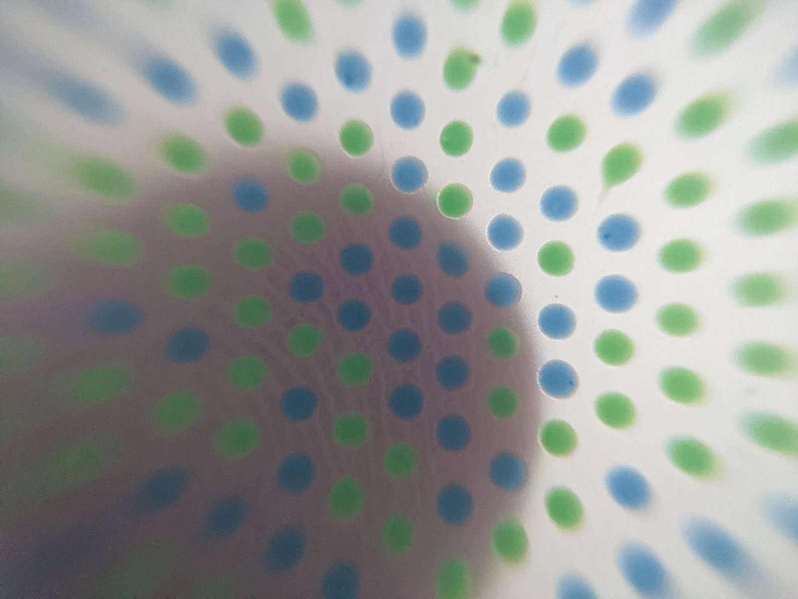
It’s pretty hard to visually directly track a fingertip just a few millimeters above a lens, fingertips have few distinct high contrast features, they are a single color and not a lot except .. fleshy. But if they deform something that’s easier to track than the fingertip itself our job is a lot easier. That’s the reason why there is a point pattern on the surface.
On top of that, we somehow need to solve our close-focus problem. Coincidentally, the clear silicone is doing an okay-ish job at refracting light. So we don’t just look through the blob like a window but we use a curved surface to collimate light like a lens. Then the pattern on top of the blob is always in focus, even when it sits directly on the glass of the lens. More about that later.
So, let’s talk about all the steps to make a blob, then see how the image processing works, and – finally – show examples of how you can or could use it in the real world. For explanation purposes, I impose some kind of order artificially, but in reality, I was going back and forth, fixing problems and improving the concept. So expect some gaps in causality.
Let’s start with the easiest part, how can we make a silicone lens?
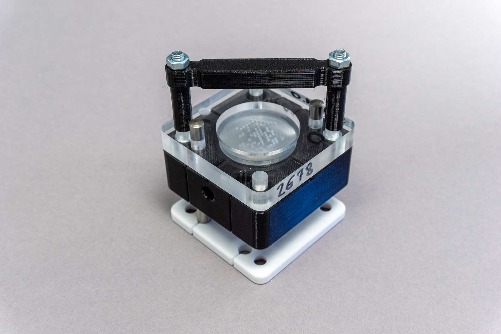
Silicone Molding
Figuring out how to mill a mold with an optical surface was an incredibly awful process, and I can’t overstate this. I covered the whole process of milling, grinding and polishing in a blog post and a video separately:
Adding Color
Once we got a silicone body, we need a way to optically measure deformation. We can do that by tracking a high-contrast pattern with the camera, but we need to put that on the surface somehow.
Silicone has a very desirable property which sadly is a problem in this particular case: almost nothing bonds to silicone, except silicone itself. Painting silicone with alcohol or acrylic-based paints is not durable, the paint simply rubs off after drying. There are only two options: either mix pigments into silicone before it cures or mix uncured silicone with pigments and use it as a painting material on already-cured silicone parts.
Side note: if the silicone is poured into an open mold the uncured silicone is easily accessible. In this case, it is possible to deposit pigments directly in the poured silicone. I tried that with water and oil-based inks and that was kind of a mess. The ink needs to be injected with a syringe into a cavity below the surface so the silicone can encapsulate the ink. If the cavity is not fully closed, the ink will leak after curing and stain the finger touching the silicone object. If the cavity is so deep under the surface that it is reliably encapsulated, deforming the surface has a considerably lower effect on the colored ink blob. All in all that brings more problems than it’s worth it.
There are two products for coloring silicone: the simple option is platinum cure silicone which cures by chemical reaction after a few hours. The alternative is a specialized silicone ink. These do not cure by simply mixing base component and catalyst but do need to be baked at a high temperature. Those are mostly used for screen printing silicone logos on polyester sports jerseys or putting text on silicone wristbands.
But how do we deposit the silicone and pigment mixture on the surface? Screen printing does not work well with a curved surface like the LensLeech top. Usually, you would use pad printing for large numbers of objects with curved surfaces. But setting up a reliable pad printing process is a lot of work for just a few prototypes.
An alternative could be to directly deposit the silicone pigment mixture with a syringe and that’s what I tried first. I modified a macro rail for moving a camera to press a syringe plunger and mounted it in my CNC machine.
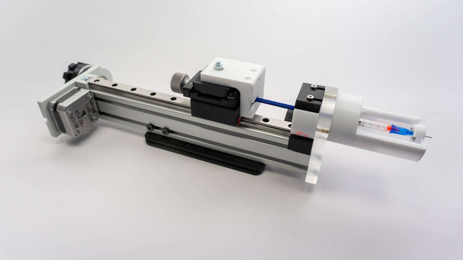
Using a very small syringe and a tiny needle allowed me to deposit silicone droplets at exactly the right height and position. But in general, it’s pretty hard to control pressure in the syringe precisely enough to get consistent tiny droplets with the highly viscous silicone mixture.
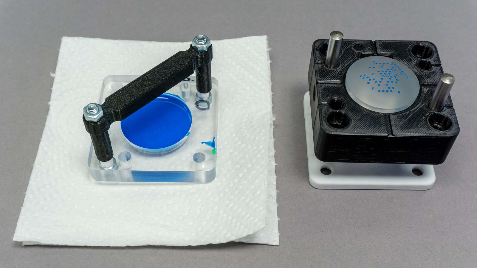
What worked well, in the end, are not flat stencils like screenprinting or deformable stamps for pad printing but rigid three-dimensional stencils.
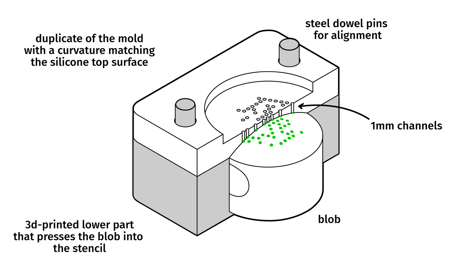
When milling a stencil from acrylic that has the exact curvature of the silicone body we can press the silicone against the stencil and get a good seal. The channels are drilled with a microdrill for PCB production. The silicone paint can be poured over the channels and after degassing plus a few minutes of rest time the stencil can be removed. Let it fully cure overnight and repeat for the next color.
As a silicone paint, I used Smooth-On’s Psycho Paint. It bonds well to the already cured clear silicone and was more reliable than using the clear silicone itself.
Adding the color to the paint is slightly more complicated. Most silicone pigment colors are sold as a liquid emulsion. The solid pigments are mixed with silicone oil as a fluid. This makes it easier to handle, measure, and mix the color. The downside: when you add too much silicone oil to your liquid silicone it may prevent it from curing. Most vendors recommend 3 or 5 percent as an upper limit. But we want to deposit tiny amounts of silicone and it still should be a strong and saturated color. I did test Smooth-On’s Silicone Pigments1. So, I did test this color at 5 percent and was not happy with the results:
Buying the pigments as solid particles and mixing them directly with the translucent silicone did work considerably better. About 10 percent of pigment powder did yield sufficiently saturated thin blobs of silicone:
The exact measurements and the procedure I used are described in the git repository
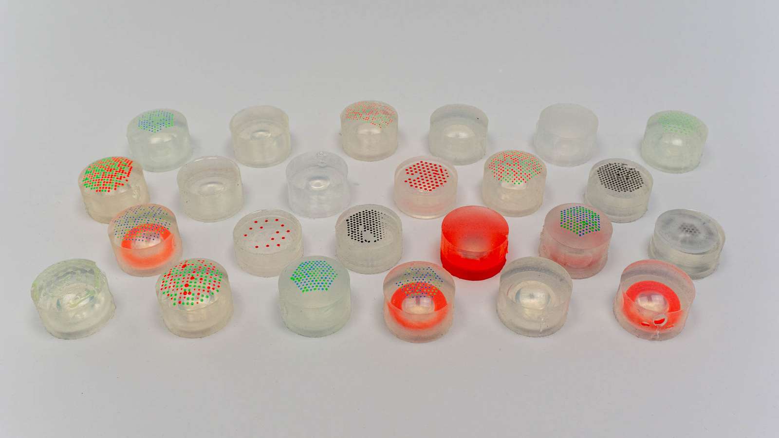
Selecting a Marker Pattern
So, we got a reliable way of adding a colored pattern to the silicone lens. Let’s look at common computer vision markers:
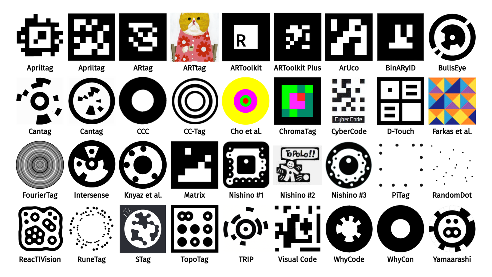
Since we are using a stencil to apply the color we can’t create complex shapes without sacrificing a lot of precision, so we’ll stick to points and can’t use any of the classic marker patterns.
With a simple single-color point pattern in a grid, we can measure deformation of the silicone. But maybe we want more?
It would be perfect if we could sense position, rotation, and deformation of the silicone blob. But every additional color requires a lot of manual work. Given just two or three colors, is there a way to make a marker pattern that allows us to match or recognize a sufficient number of points to get at least the rotation?
About a decade ago the company Anoto released a ballpoint pen with a built-in camera and a special type of paper. The paper had a very faint point pattern printed on it that allowed the pen to see its position on the paper when writing. The point pattern patented2 by Anoto did encode four different numbers as deviations from the center.
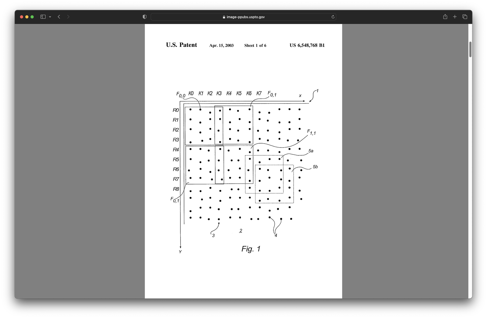
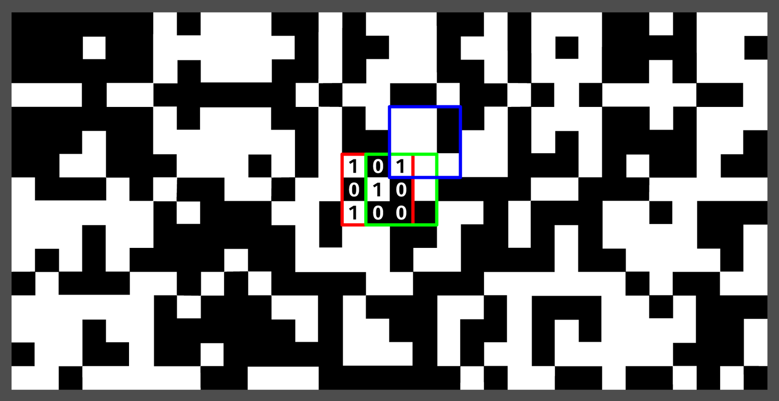
These numbers were arranged in unique patterns usually known as a two-dimensional DeBruijn sequence. In the simplest case, it’s a grid of only two numbers (the black and white squares). Each window of a specified size (3 by 3 in this case) can only be found once (the red square). If we shift in any direction (green and blue), that’s a new unique window.
Anoto could use four different numbers and encode them as offsets because paper is flat and rigid. For our soft and deformable surface, we’ll need to use color. Another issue is geometry. With a rectangular grid, we’re wasting a lot of space and sadly, we don’t have a lot. With a standard phone camera, we see about a centimeter in diameter of the blob’s surface. And the larger the points, the more reliable our image processing will be. So we’ll do something that’s a lot of work for a marginal improvement: we’ll do our own, slightly more space-efficient pattern.
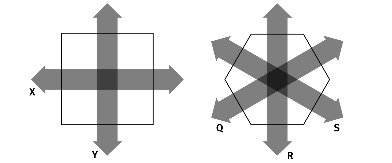
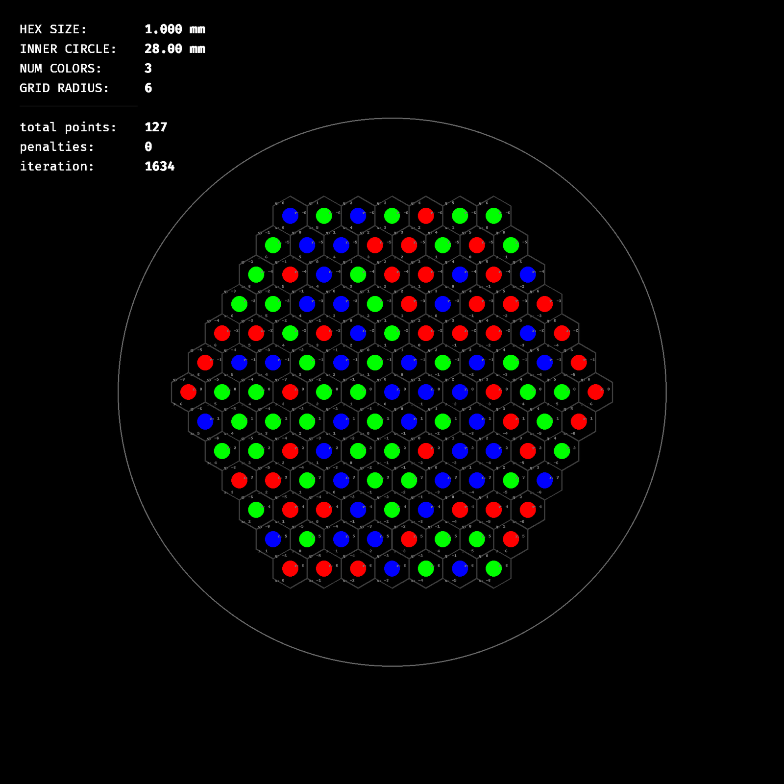
The optimal way to fill a plane with circles is not rectangular but hexagonal packing. The only problem is that on a grid you can move in two directions and your blocks are always rectangular. On a hexagonal plane you can move in three directions and your “blocks” are hexagons.
For a grid, it’s pretty easy to find really large two-dimensional DeBruijn sequences computed by other people. For hexagons, you can’t. So, one option would be to take the DeBruijn math and combinatorial tools and adapt them to add another movement axis, or … we just bruteforce a pattern. The blob we use is rather small anyway so we may be getting away with just making up a few million solutions and testing them instead of actually computing them in an elegant way.
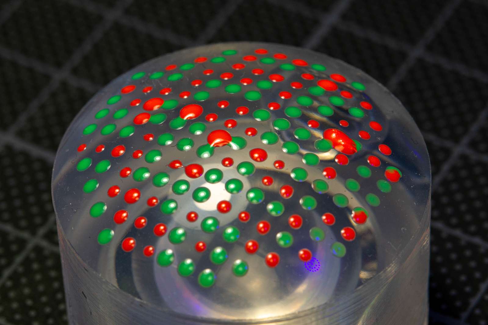
And indeed, it took a few days, but we’ve got a solid selection of patterns. The bruteforcing script tries to build a valid pattern with no duplicates from a random seed and then judges it. When you rotate a hexagon and find it somewhere else in the pattern, the score is reduced. In the end, we don’t get an optimal pattern with just two colors, but it should be good enough.
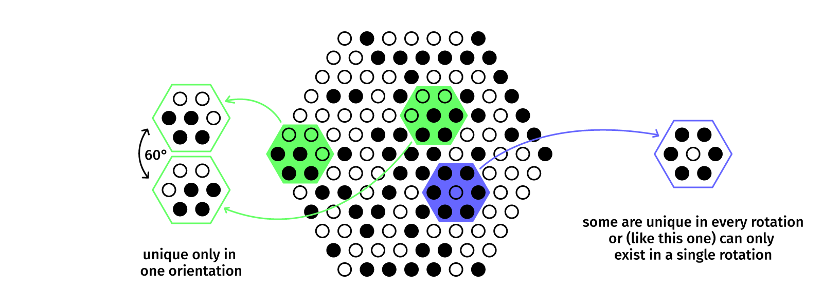
If we add a third color we find a duplication-free pattern in a trivial amount of time, but using only two colors is such a benefit for detection stability that we’ll keep it that way.
Computer Vision
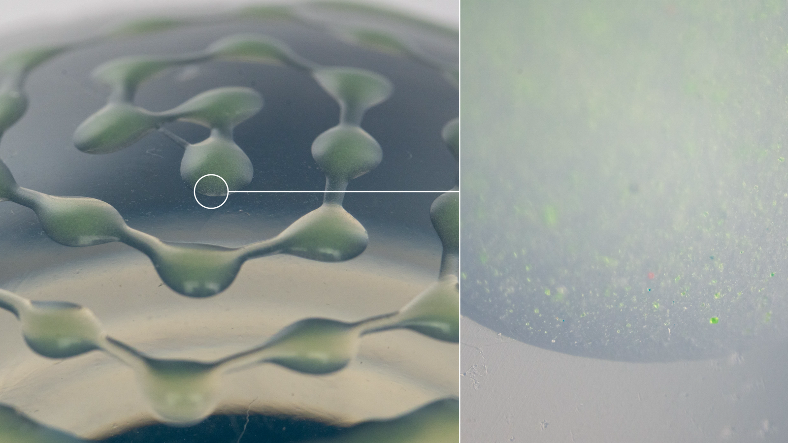
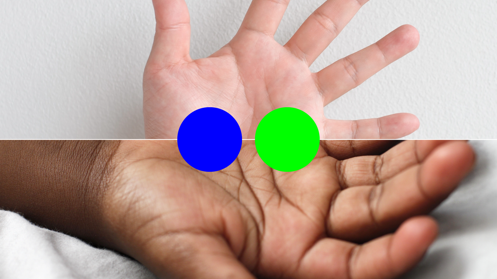
We got a silicone body with a working pattern. Now we just need to take care of image processing and the first step is to find the points and group them. The green and blue color-coded points give the best contrast to fingertips among the range of human skin tones.
But the tricky part is not only finding the points but differentiating between them in a wide range of ambient illumination situations.
By using a diffuse top surface for the blob we can make that problem a bit easier. The ambient light is out of focus anyway, but now even a fingertip a few millimeters above the surface is nicely blurred.
Detecting the points in the pattern is slightly more complicated. If we look at our input data as pixels in a three-dimensional color space we can see that we got two nice distinct groups so that should be easy to differentiate. I am not using red, green, and blue here but the HSV color model with hue, saturation, and a brightness value which makes a lot more sense in this case. Same colors, other mathematical representation.
But once the illumination changes or the finger touches the surface the auto-white balance algorithm takes a few moments before adapting. We can’t expect good results with fixed thresholds for segmentation in this case, so we grab something from the very basic computer science toolbox and use k-means clustering to differentiate between these two groups.
But if we look closely, probably we don’t need to care about saturation and value, only hue makes really a difference. So, we’ve got a 1D clustering problem, … which … looks a lot like a histogram. And since we got only two groups that means adaptive thresholding.
So we do a bit of fixed thresholding to get the points, extract hue values for these points, apply Otsu’s method to find a threshold … and we got two solid sets of points. Using Otsu’s method instead of a k-means with randomly initialized starting points takes about one-fifth of the computation time, so it’s an acceptable tradeoff.
Quick side note: Interestingly, there is by now an improved approach to Otsu’s 45 years-old method with a generalization and tunable parameters.
In general, segmentation and classification of the point pattern is … well, there is room for improvement, both in terms of speed and accuracy. But it’s good enough to work as a demo and it’s …

Once we got all the colored points, each one is grouped with its closest six neighbors. Since we don’t know the correct rotation, we try to find matches for all six possible hexagons in our pattern.
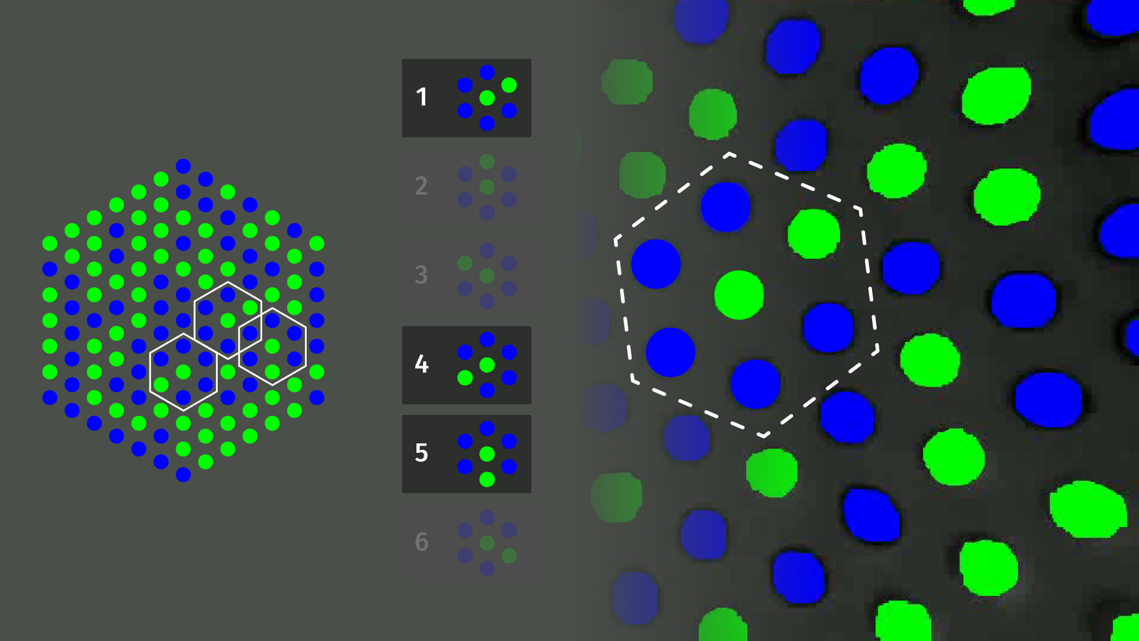
For each hexagon, we check a lookup table and try to find a position in our pattern that matches up with the highest number of other hexagons. That’s the most inefficient step of the detection pipeline and if a pattern would contain each hexagon only once, no matter the orientation, this would not be necessary at all. But for that, we need three colors and that’s more costly in fabrication and less reliable when segmenting points and background.
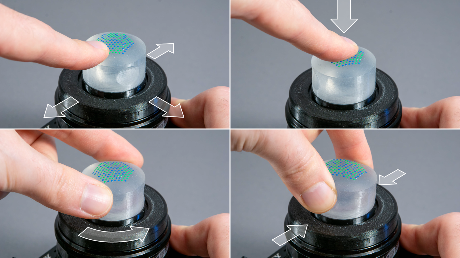
Once we have our point matches, we can compute input gestures. Rotation is found with a 2D version of Kabsch’s algorithm. Translation can be detected with the centroid of all detected points. Deformation by squeezing the sides is detected using the average circularity value for all hexagons. Deformation by pressing on the top can be seen when thresholding local maxima in point distances.
Application Examples
What can we actually do with this now? I built three application examples. The first two are only concepts, but the hybrid viewfinder is a fully functional device.
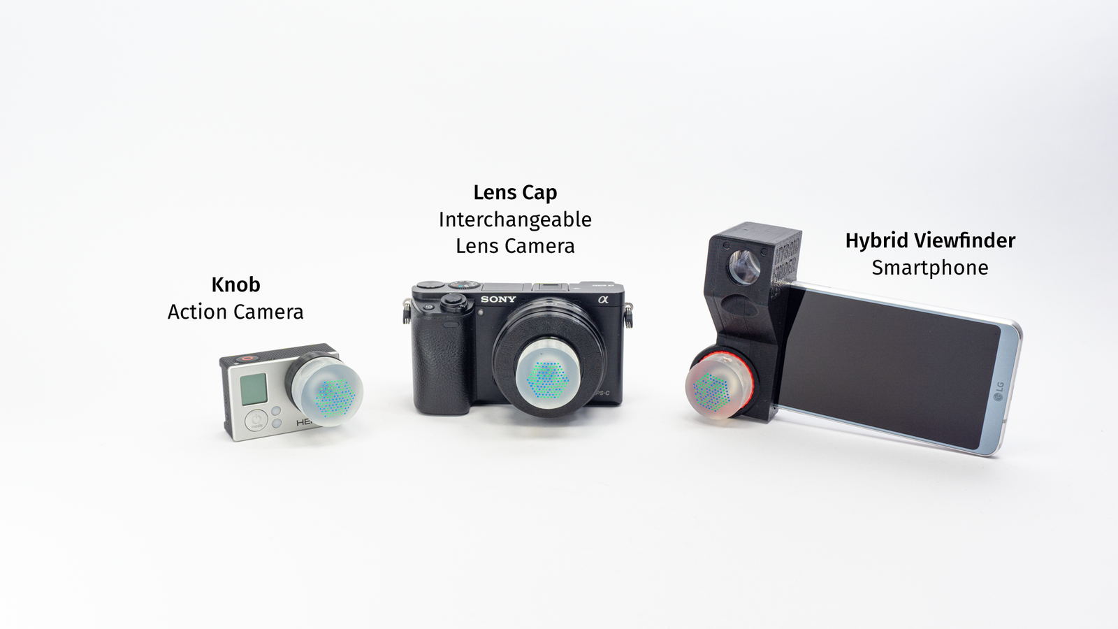
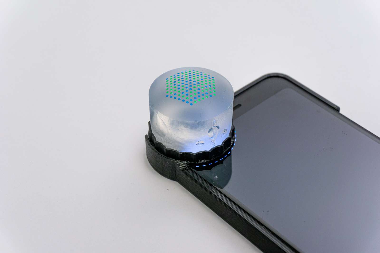
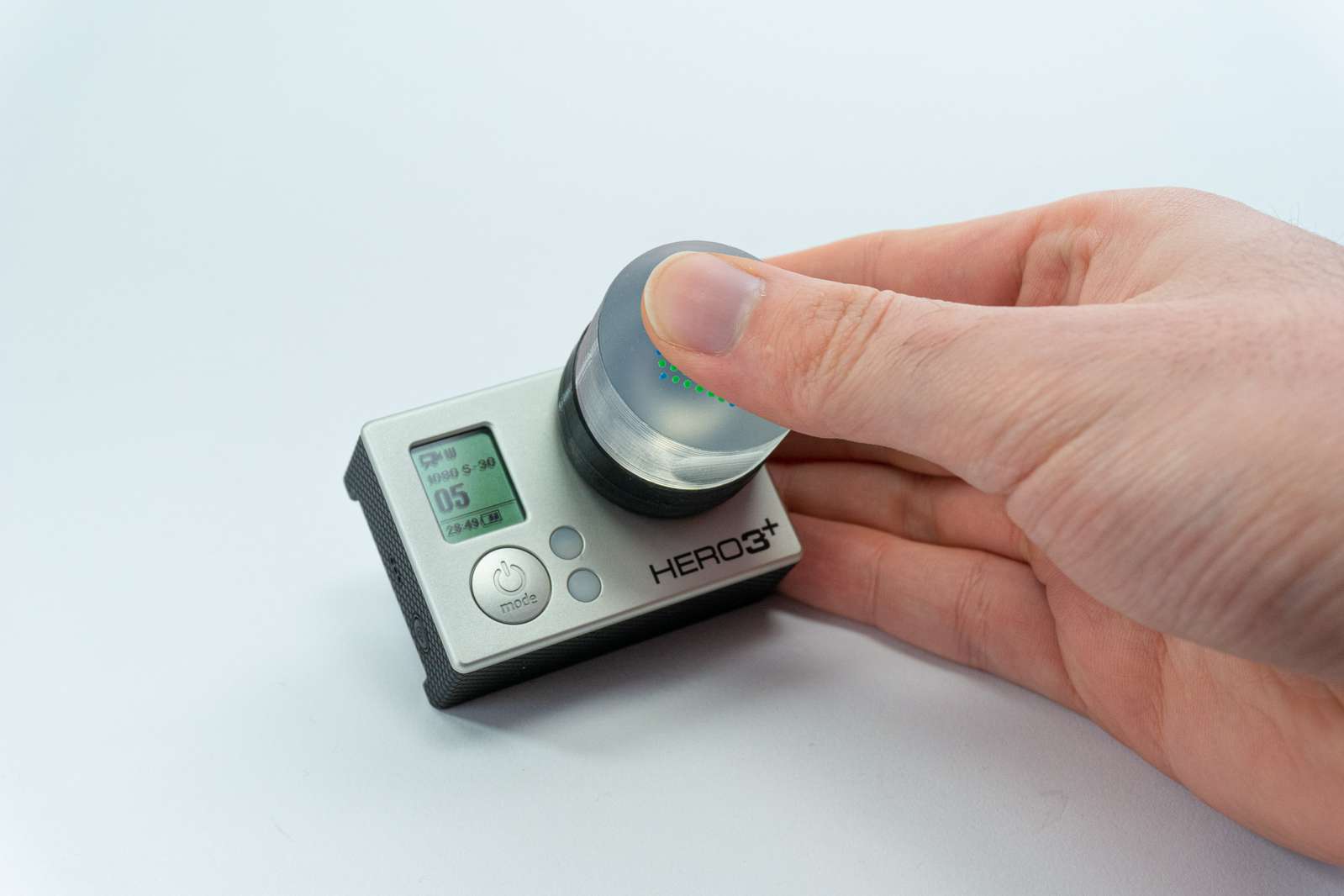
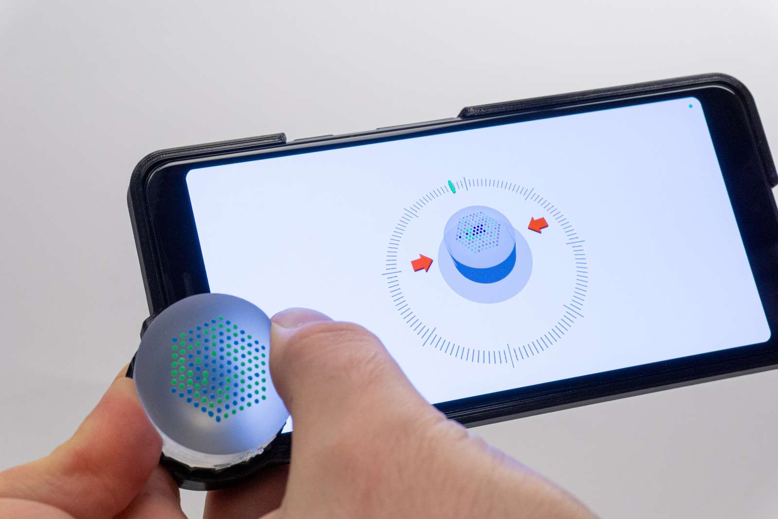
Imagine you got a tiny device with a camera. Not a lot of space for buttons, not a lot of space for a usable touchscreen, because it’s mainly a camera. Usually, you set the settings with a smartphone app, but sometimes that may not be an option. You can combine the LensLeech with a hard plastic ring that slides over the lens and you’ve got a rotation knob and button.
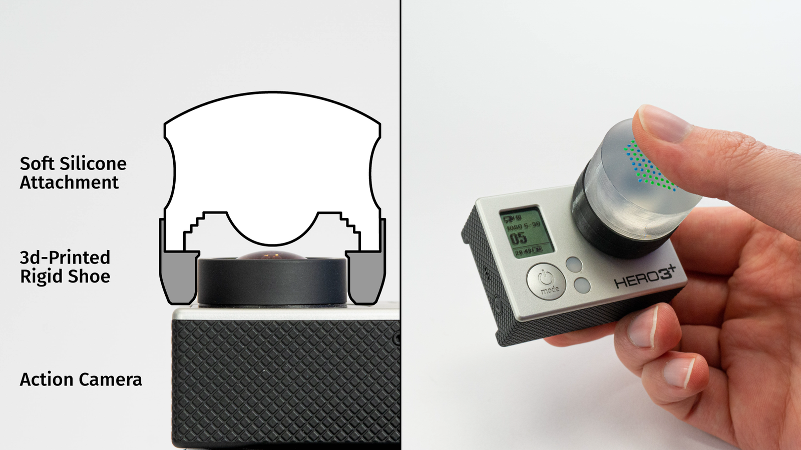
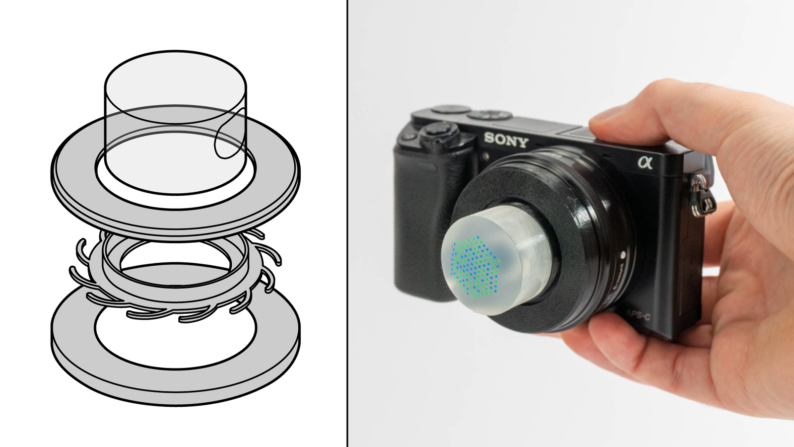
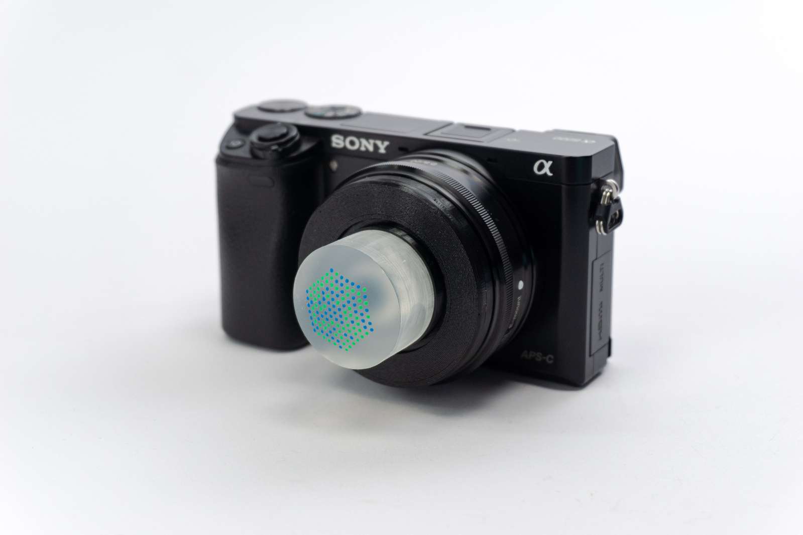
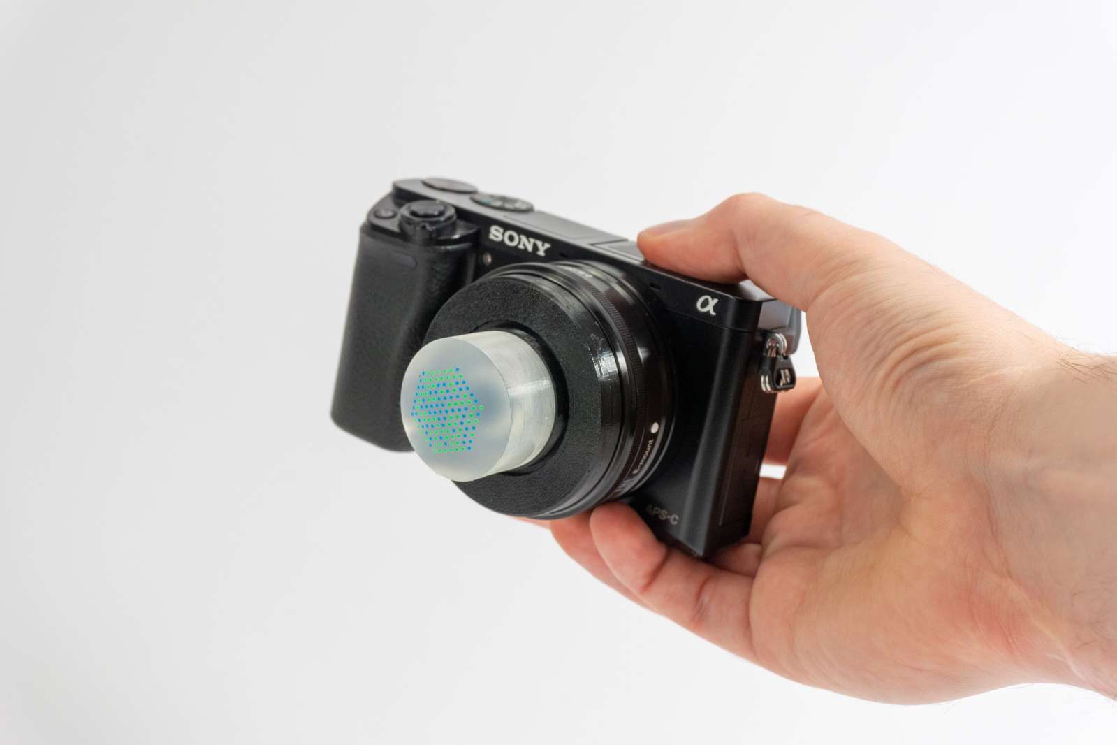
That works for larger cameras as well. Unlike a smartphone, interchangeable lens cameras are single-purpose devices, you capture photos or videos and that’s it. But often one might change menu settings or browse pictures with an attached lens cap. By integrating the silicone body into the lens cap we can add additional input elements in front of the camera.
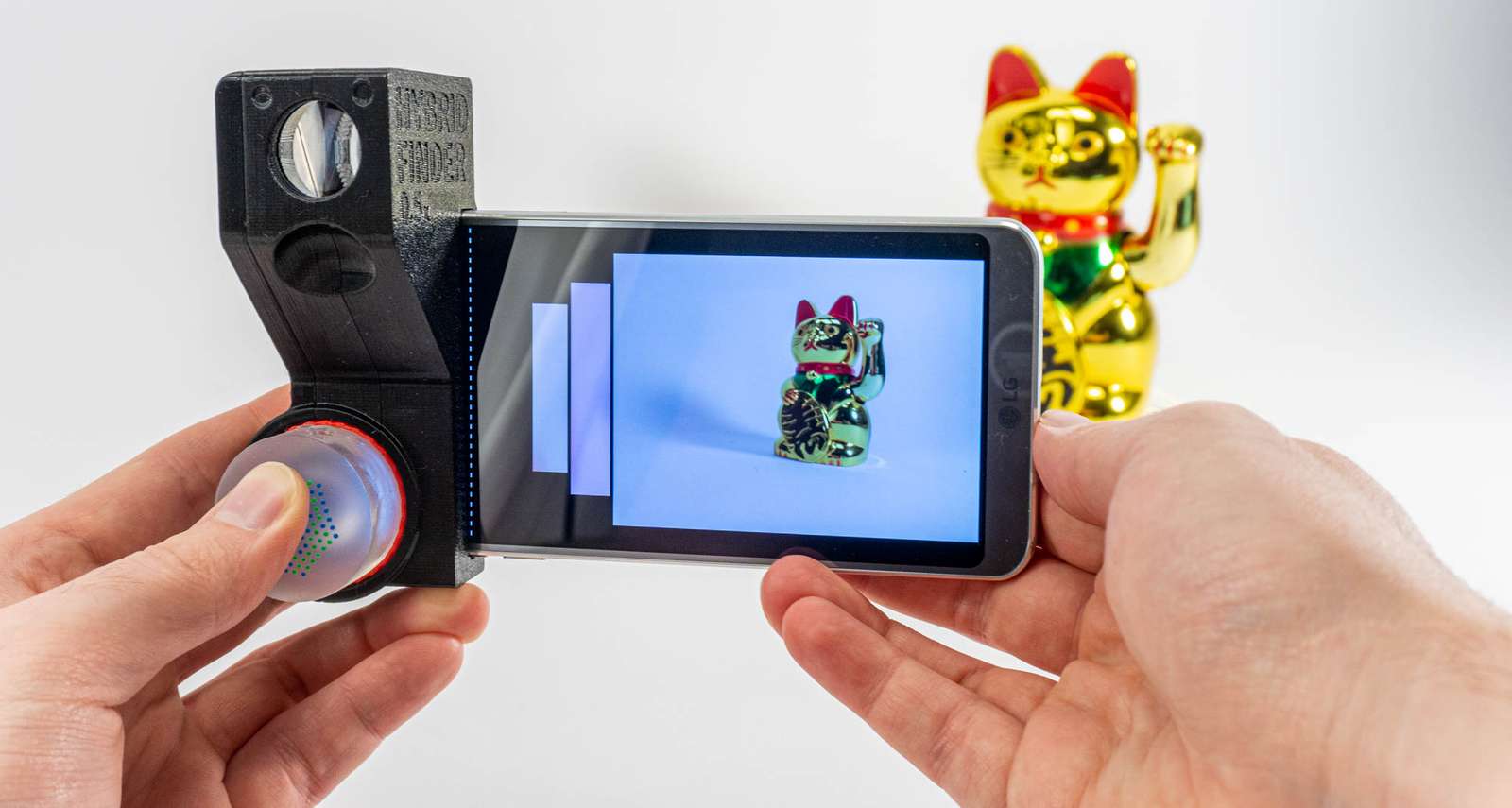
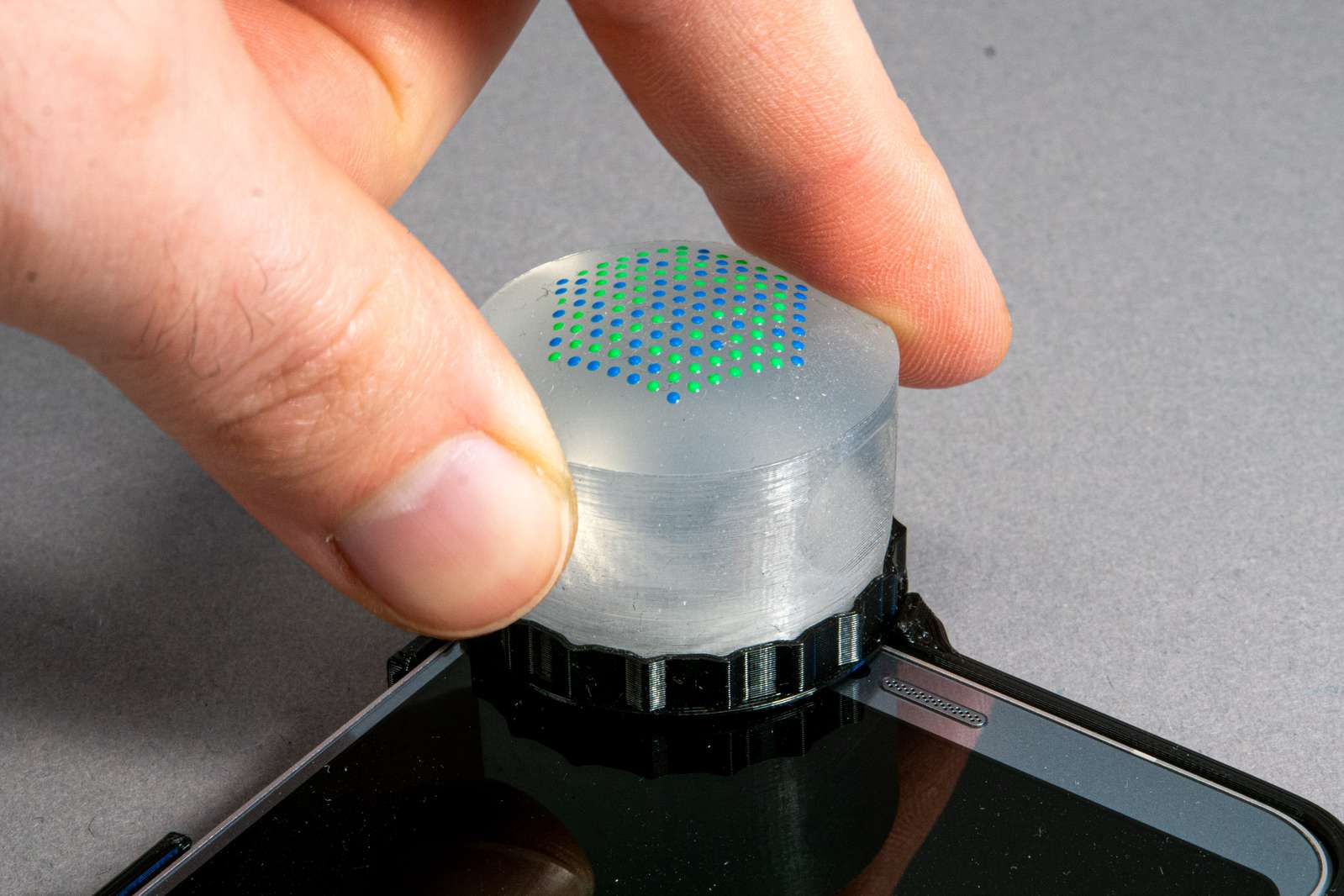
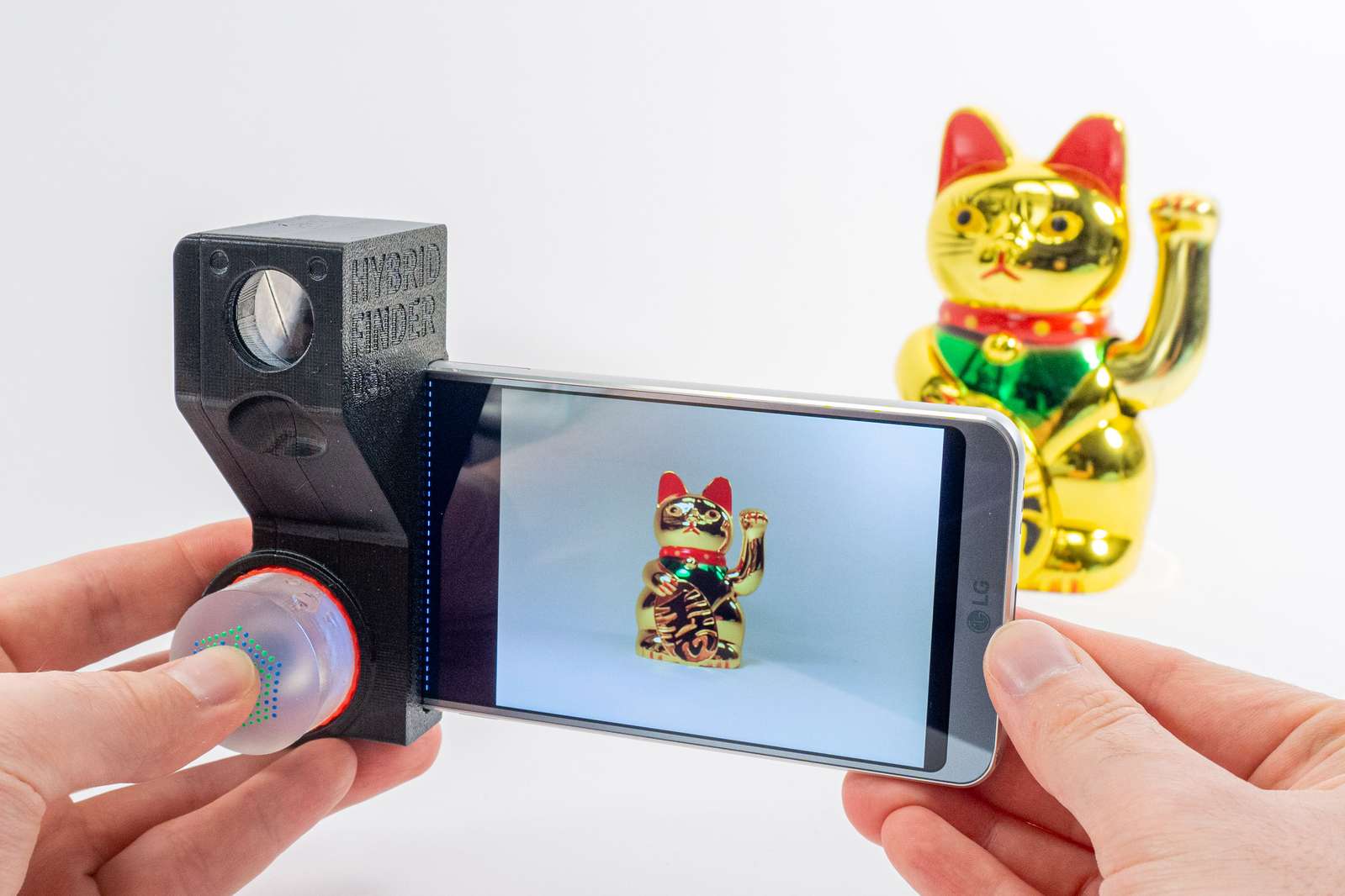
But optical attachments in general can not only provide input but output as well. Imagine you got a smartphone and you want to take photos. Maybe it would be nice to have all the advantages of classical viewfinder cameras while making use of the high-quality camera you are carrying around in your pocket anyway.
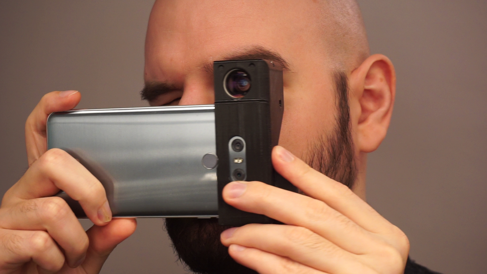
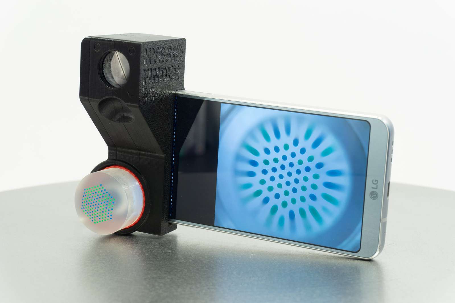
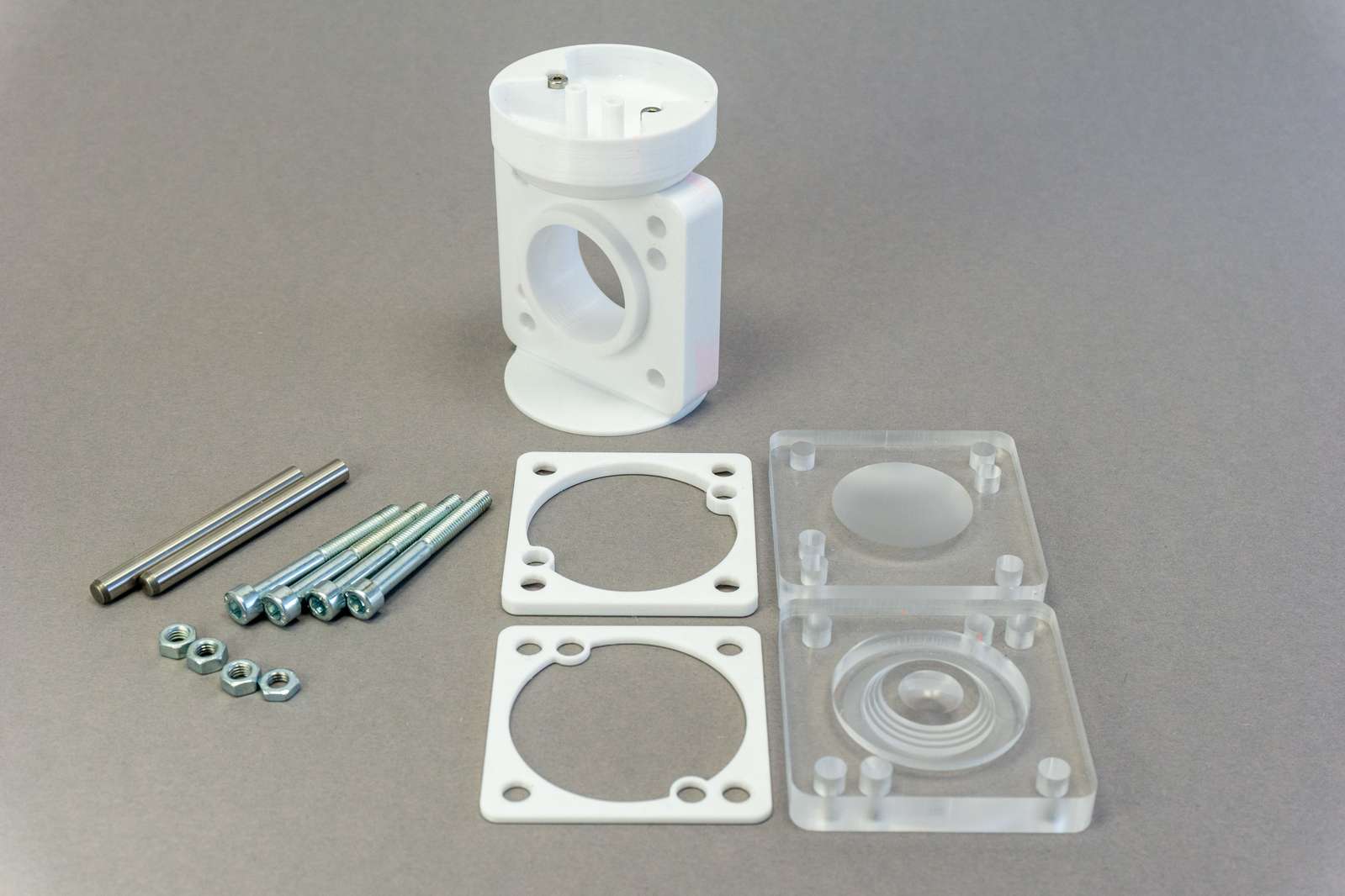
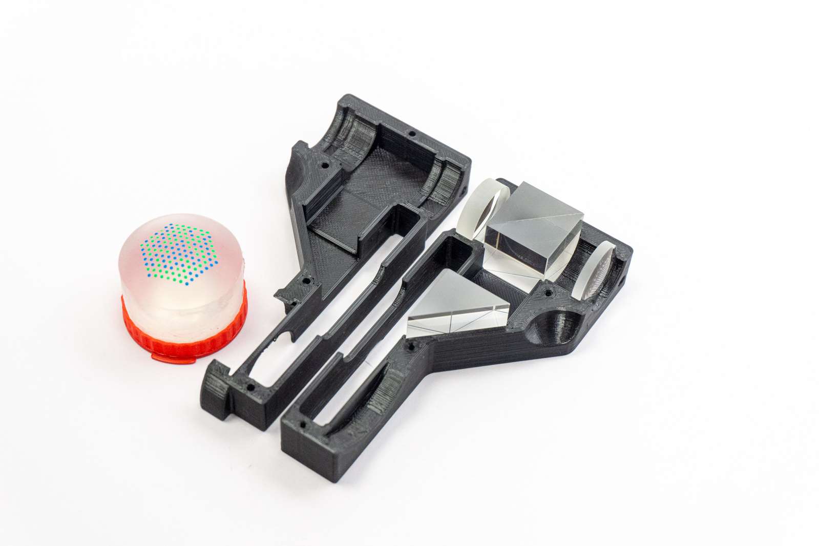
We can combine a classic optical viewfinder design with some prisms and beamsplitters and create a hybrid viewfinder.
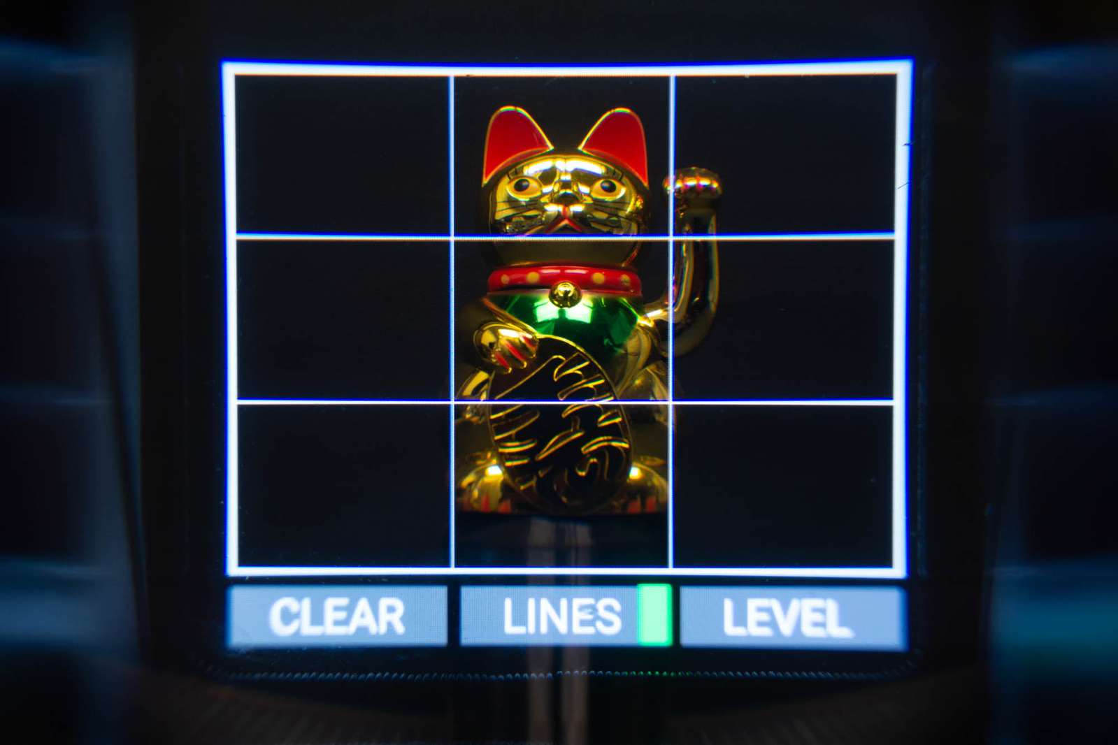
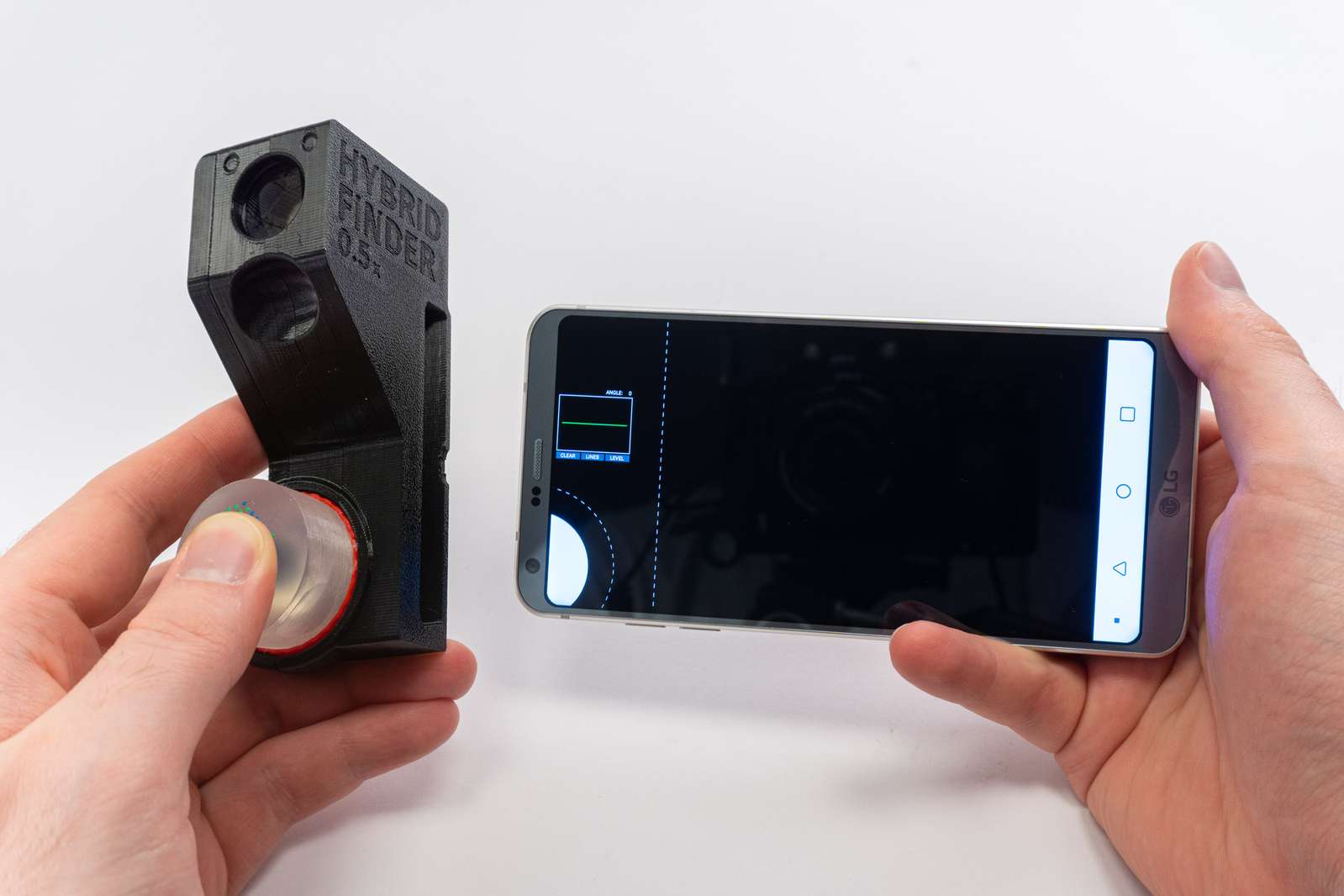
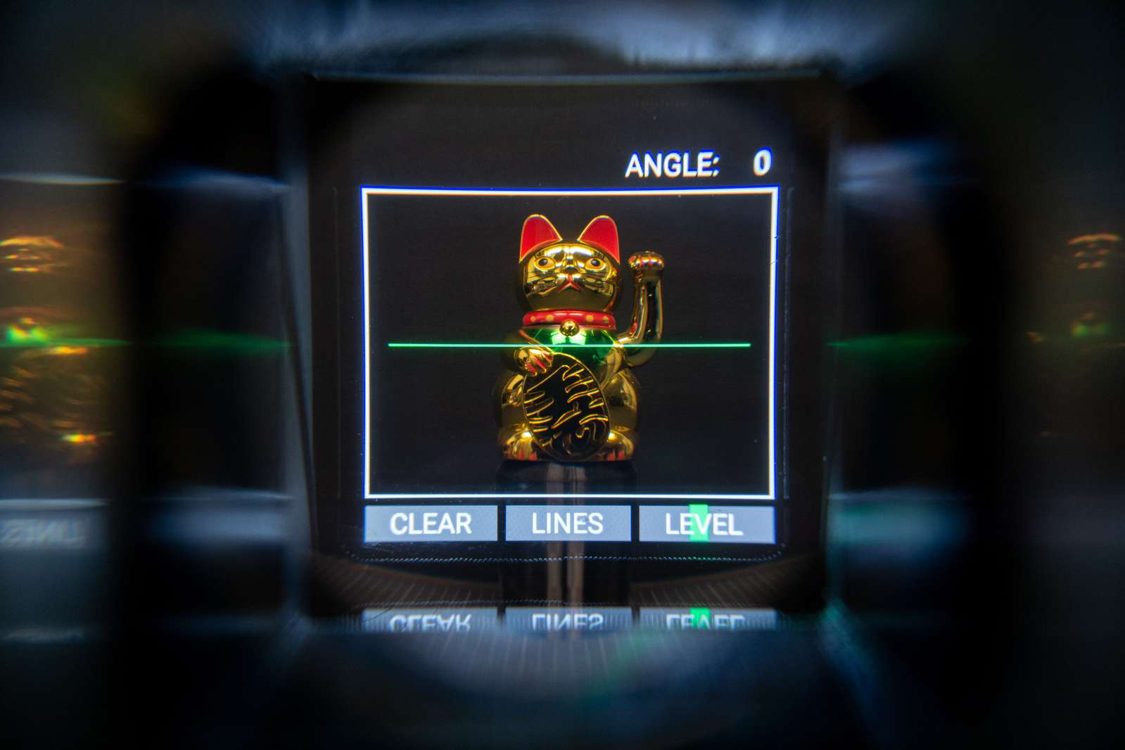
The viewfinder attachment can be slid over the phone. A prism redirects a section of the smartphone display into the viewfinder as an overlay.
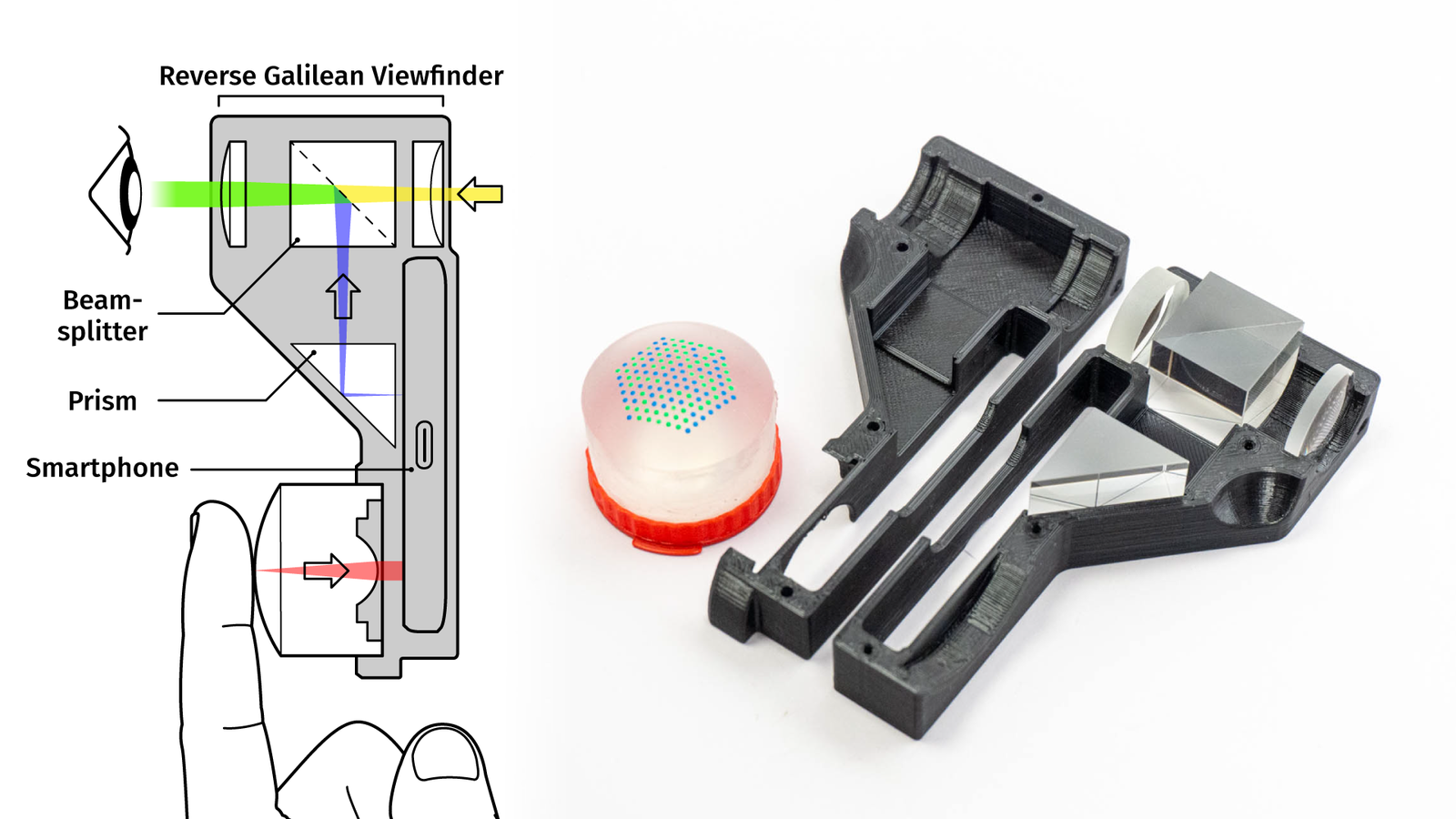
The LensLeech sits on the front camera, so by rotating the LensLeech it’s easy to select an overlay type, for example, compositing frame lines or a digital horizon.
By pressing the silicone you can take a photo. And all of this can be done without the touchscreen so you can use your phone like a classic camera.
In case you’re wondering how that works on the optical level, I made a video about viewfinders in general and the hybrid viewfinder in particular:
Problems:
The LensLeech does check a few important boxes for on-lens interfaces:
- safe to use near or on optical components and providing credible reassurance to the user about this. This is a prerequisite for user acceptance.
- non-invasive, requiring no hardware modifications of the host device or its camera. This ensures compatibility with existing devices that benefit most from optical attachments.
- passive and unpowered, requiring only ambient illumination (if possible) to reduce size and complexity.
- universal; compatible with arbitrary camera/lens combinations across a wide range of device types.
The fact that it is completely passive means it requires ambient illumination. One problem with that is tinted light. The brain is pretty good at discerning color casts and recognizes a white object as white, even if it reflects blue or yellow light.
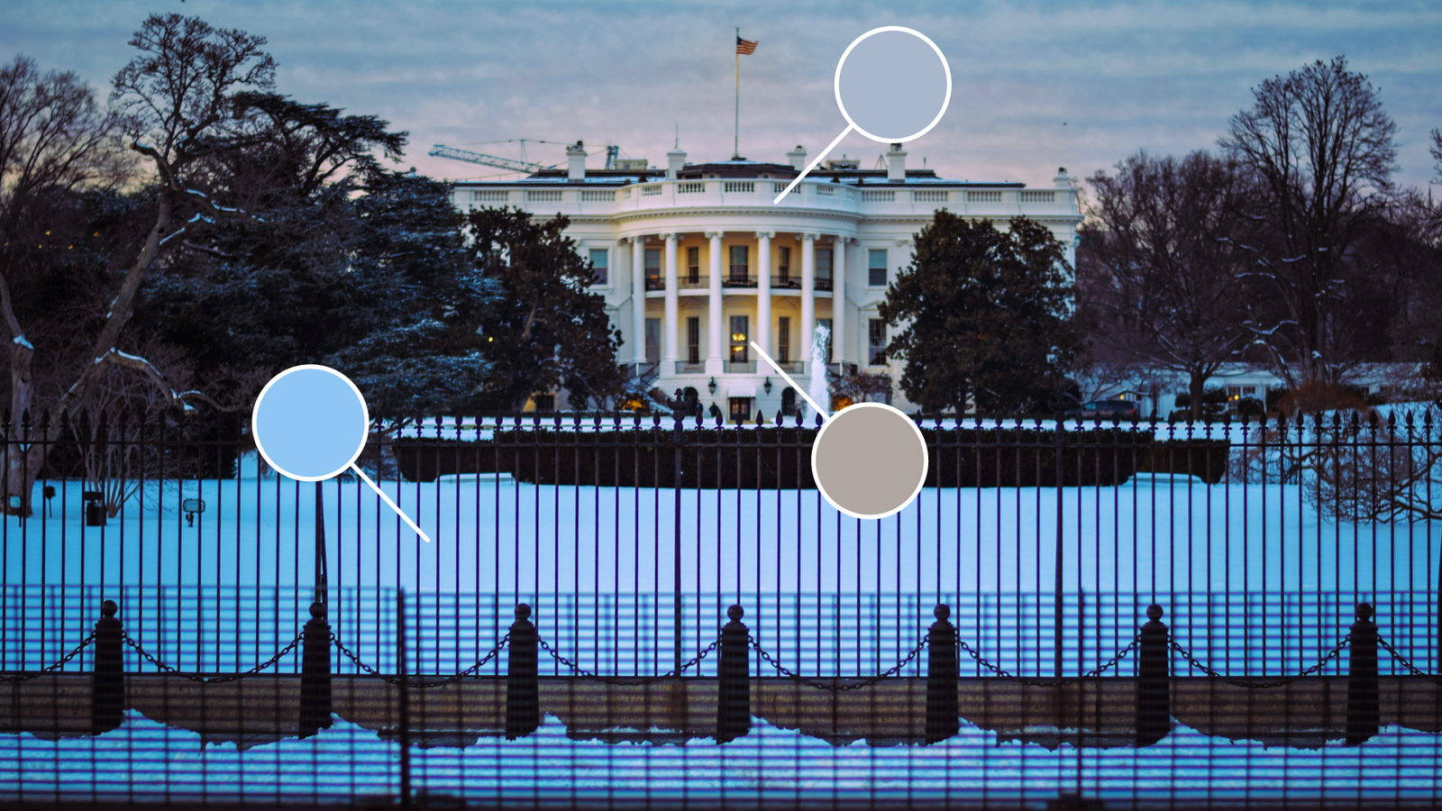
Cameras use an auto white balance algorithm for this and most of them perform worse with a LensLeech on the lens.
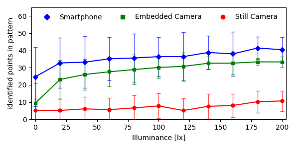
Another issue is that there needs to be a minimum amount of light to work at all. It makes sense to measure performance for light intensity and color tint at the same time to resemble real-world situations. I did place four different cameras in auto-exposure mode in front of a display in a dark room and showed 1000 pictures of different scenes at different brightnesses.
I measured the illuminance in lux and plotted how many points of the pattern could be detected (including false positives). For a number of reasons, the plot looks slightly odd and is a bit too optimistic for the dark regions, but basically, if it’s brighter than 150 lux it’s mostly usable. 150-250 lux are the average indoor lighting conditions, so lowlight performance is mostly acceptable.
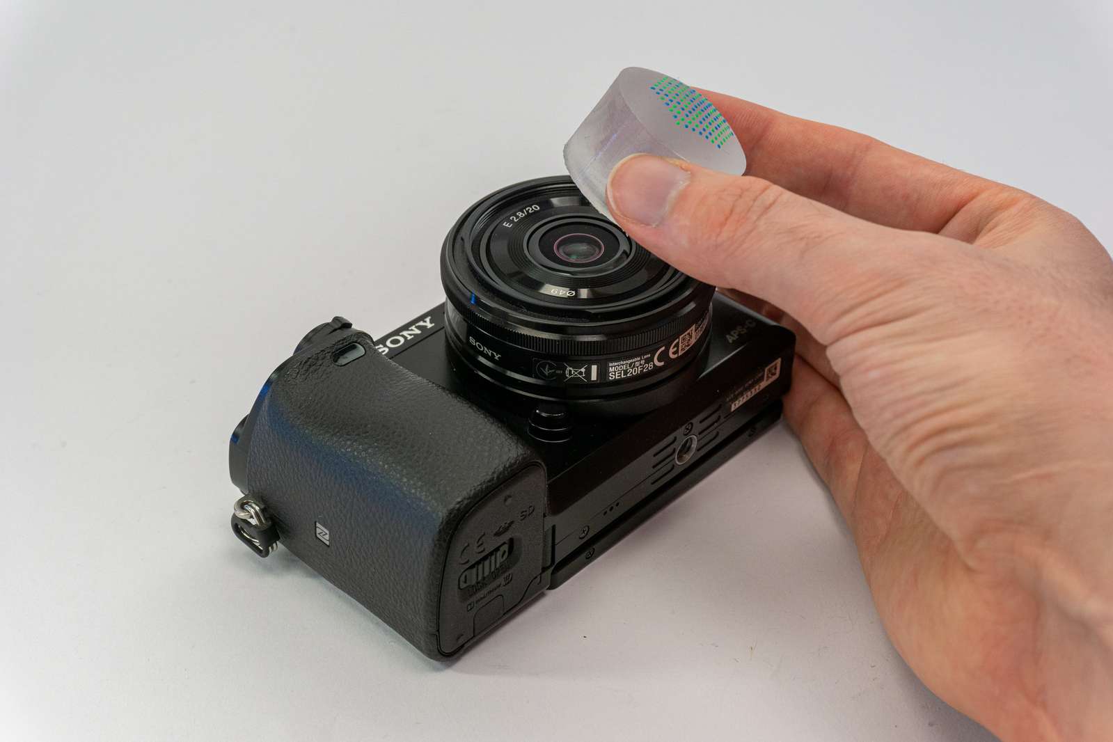
There is a third problem and that’s pupil size. Every lens has an entrance pupil. That’s the image of the narrowest point of the lens (usually the aperture) as seen through the front of the lens. For photographing objects at infinity, the entrance pupil doesn’t matter. But for very close objects does make a difference.

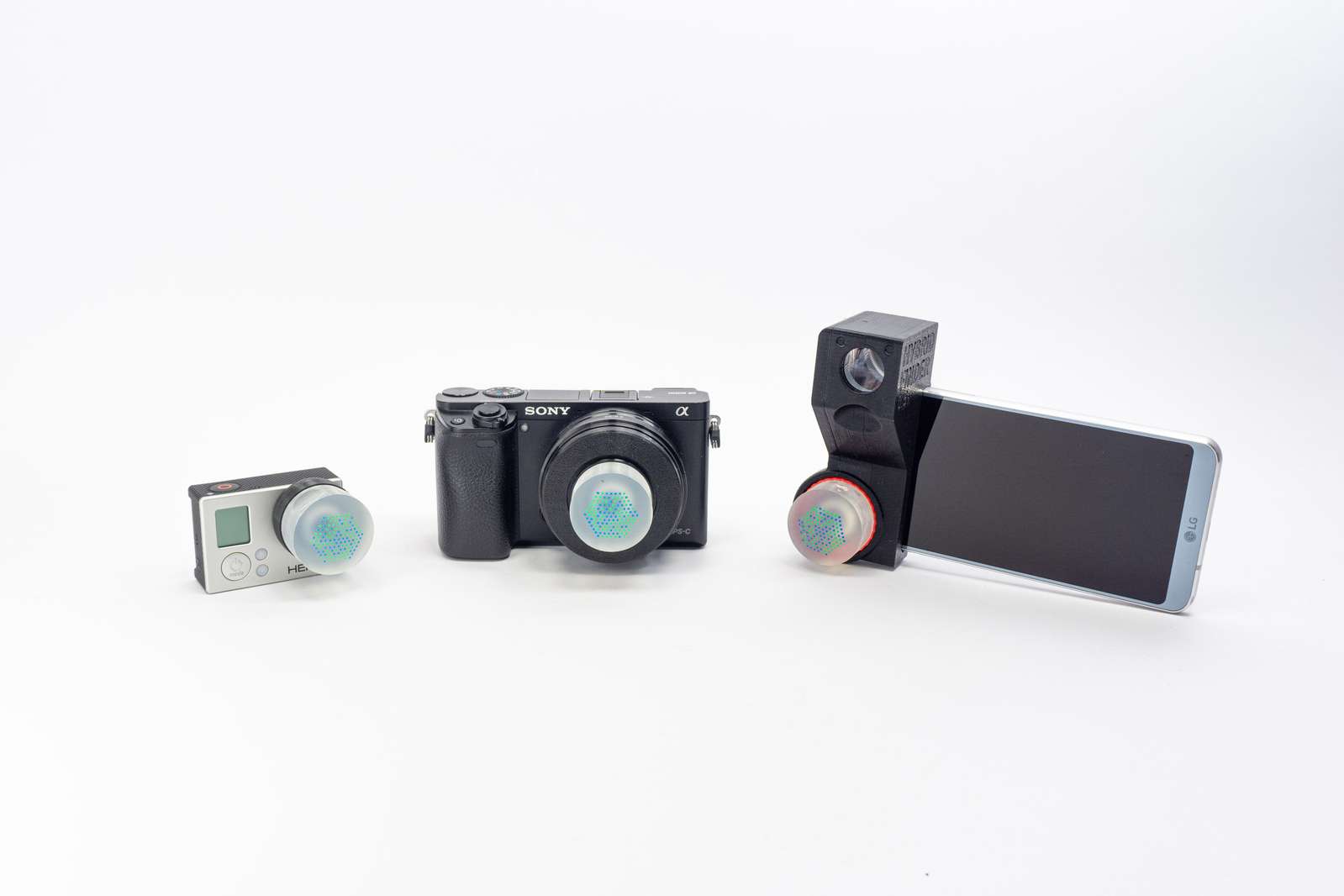
If the diameter of the pupil is considerably larger than the diameter of the silicone lens of the LensLeech, the camera won’t see enough points of the pattern. I’ve got three lenses here, all three of them have the same field of view of 84 degrees (or about 24mm on a full-frame camera):
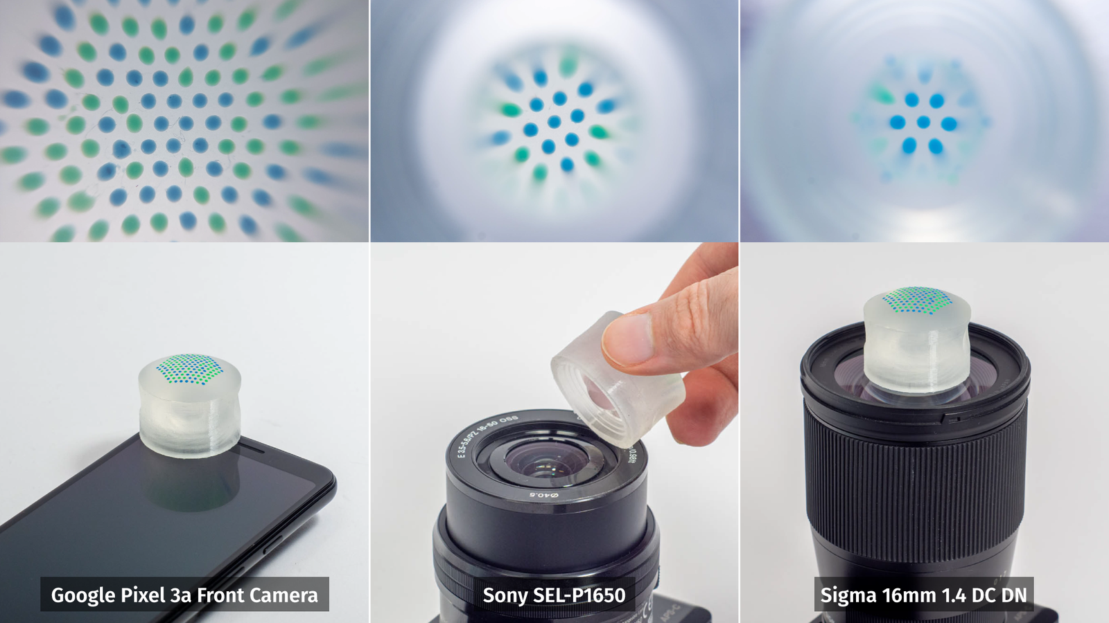
Only two of them are LensLeech-compatible. Smartphones and action cameras work perfectly, for other cameras it really depends on the size of the lens.
Future Work:
Right now there is only a single kind of LensLeech, which can be used as a knob or a joystick. One option would be to sense fingerprints as well. A clear silicone surface acts very similarly to an optical fingerprint sensor if the illumination angle is correct. For some situations, screens of devices or LEDs would be able to provide the necessary light to make it work. Then you could retrofit a fingerprint sensor to a smartphone or camera lens cap. Maybe not so much for authentication, but for triggering different actions with different fingers.
Another issue is the relatively small field of view due to the silicone lens. If we can change the optical system to make use of the full surface, measuring the local deformation allows to use a LensLeech like a touch surface.
Conclusion:
Does all of this make sense? Depends. First and foremost it’s an idea. A concept. It’s not a product that you can buy or that anyone should buy, but it proves that there is a technical way of retrofitting a multitude of existing camera-based devices with slightly more expressive input methods. On top of that, there is a whole world of soft robotics research. Robot arms and robot bodies made of soft silicone. User interaction is often measured only with electrical resistance sensors, but direct, vision-based interaction with soft silicone blobs embedded in a soft robot’s body may be an interesting option.
The next step would be to ask people if they would actually trust the squishy silicone blob not to scratch their lenses. There is kind of a culturally ingrained respect for shiny lens surfaces and people are extremely careful around those. But that’s some future work.
More info:
-
Software, hardware, 3D models, slightly more detailed explanations about the fabrication process and everything else is open-source in a GitHub repository.
-
For a less verbose take on this project (and a lot more related work), see the paper: https://arxiv.org/abs/2307.00152
-
For a visual explainer, refer to the YouTube video: https://www.youtube.com/watch?v=lyz52IzMcnM
If you might intend to do something similar and have questions, feel free to reach out.
Further reading:
- Soft silicone sensors are a very interesting topic. For a very high-level intro, there is a video about GelSight sensors3 from Steve Mould. For a detailed overview, I can recommend the reviews by Shimonomura and Abad et al.
Gallery:
Fine print:
This post and all images/videos are licensed under CC BY.
(If not indicated otherwise. CC images/videos published by other people with different licenses are labeled as such. Public domain images are not labeled.)
You are free to Share — copy and redistribute the material in any medium or format and Adapt — remix, transform, and build upon the material for any purpose, even commercially. But you need to take care of Attribution — You must give appropriate credit, provide a link to the license, and indicate if changes were made.
See the FAQ for more info.
-
I have no clue what’s wrong with the people at Smooth-On, but why do you call your product “Silc Pig”? Really? Anyway, applies to their semi-translucent silicone as well. ↩
-
The video gets some details wrong, though, so take it with a grain of salt. ↩