Making Flexible Lenses at Home
15 Oct 2022Have you ever felt the need to make flexible and squishy lenses from silicone? Do you only have a 3d printer and a very basic CNC mill at home? Then you may be the target audience. What I’m writing about here only works for concave molds which make convex-convex or plano-convex lenses and I admit that whole thing is certainly something of a niche topic, but I mean, that’s what the internet is for. Niche topics.
Making a lens or a lens mold on a CNC mill might not always be the best idea, but sometimes it may make sense. Especially if you are working with acrylic or aluminium as a material and your expectations are somewhat limited. Good enough is often all you need.
But, a quick disclaimer: I’m neither a machinist nor do I have a clue about optics, I am just someone with a problem and trying to solve it somehow. I’ll explain what did work well for me, if you know more about that stuff your feedback is much appreciated.
So, back to the problem: For a project I want to make some lenses from soft silicone. For that I need the inverted shape of the lens as a mold so you can pour the liquid silicone into it and once it hardens you got your soft lens.
The problem with any optical surface that should work as a lens is that you need both a perfect overall shape and a perfect surface quality. If your shape is distorted, your focal length may be off or you get some horrible imaging artifacts. If your surface is rough and has tiny scratches you will get fogging or loose contrast.
You can buy high-quality lenses for a bit of money covering most diameters and focal lengths from Thorlabs or Edmund Optics. You just buy the negative version of what you actually need and put it into your mold. That’s pretty nice because you get your perfect shape and optically clear surface as a part of the lens for an okay-ish amount of money. The problem is: it’s glass. Borosilicate glass. And that’s about three-quarters silicon dioxide. Silicone (with an E) basically just sticks to silicone and … silicon. So itself and glass. Instead of glass lenses, you can purchase plastic lenses as well and they will be considerably less expensive, but I couldn’t really find a supplier with a decent catalog that actually sells to customers directly and not just business-to-business.
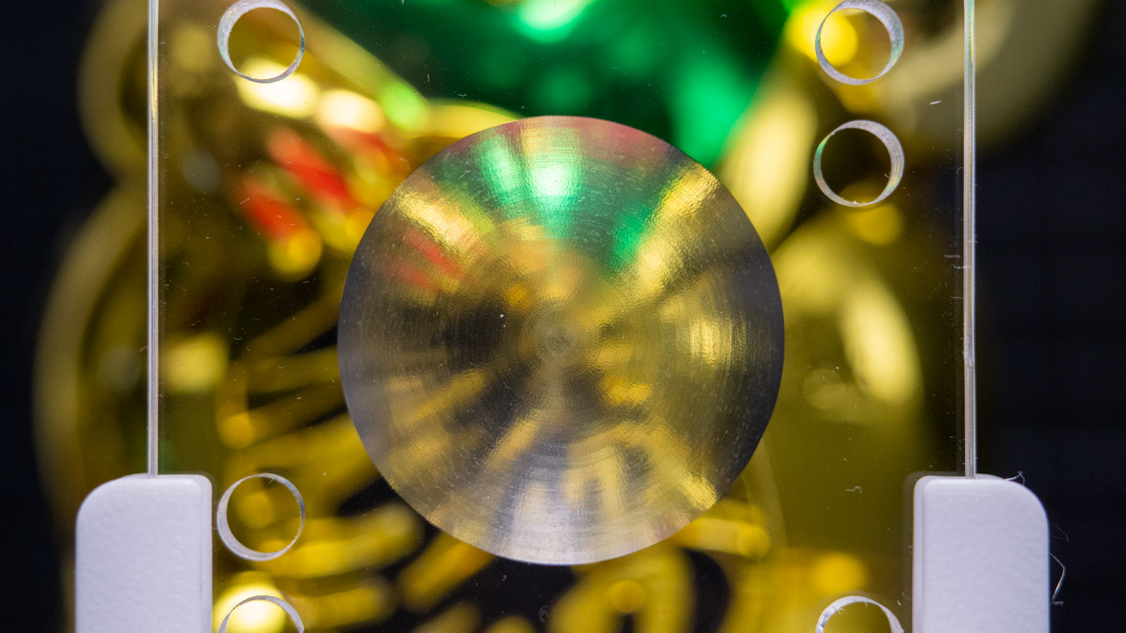
I did a few tests with mold release to coat a glass surface for silicone molding and see if I could make it work anyway, but the mold release agent (either sprayed wax or liquid wax) just messes up the optical surface (the lens on the top has been waxed, the bottom one is clean).
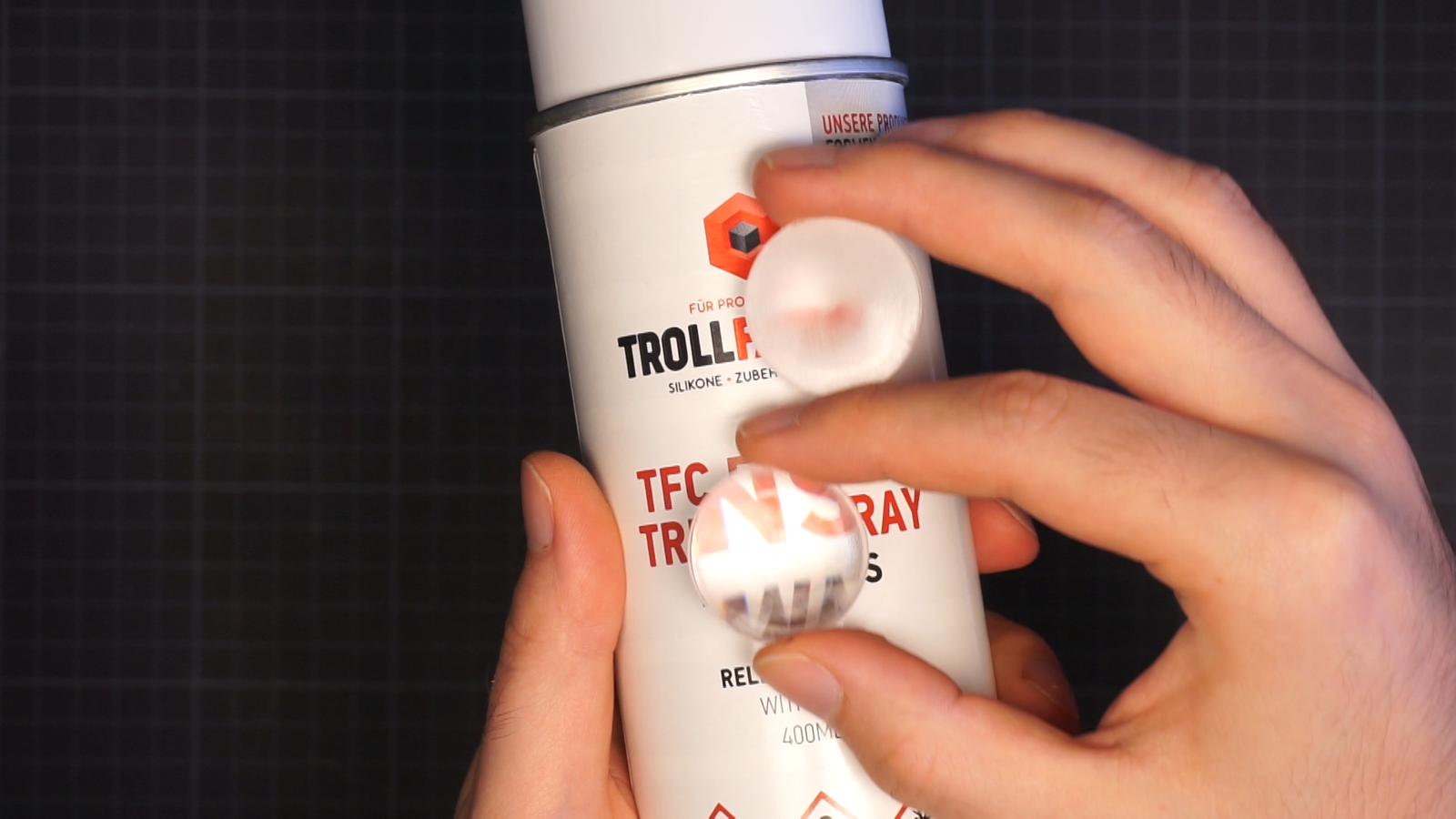
The molding and separation work fine, but the surface gets a texture so it’s not acting as a lens anymore.
So, almost done with the introduction but before I start, there are a few youtube videos on this topic that I can highly recommend:
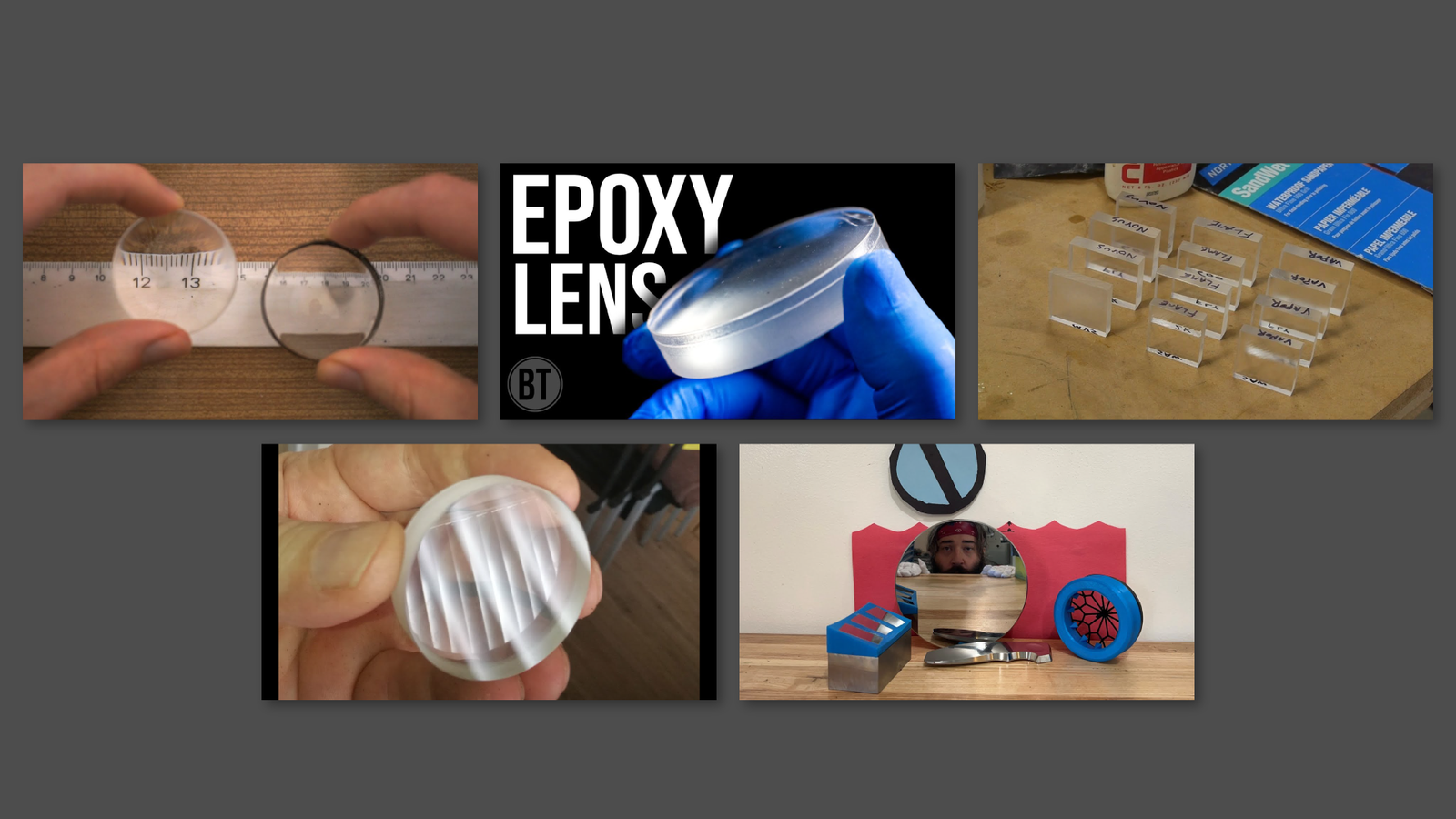
- Making Lenses with a CNC Router Part 1/Part 2 by Brauns CNC
- Optical finish for acrylic – vapor polishing and other techniques by Applied Science
- Making DIY Lenses with Epoxy by Breaking Taps
- Improve your polishing with 3D printing by Adam the Machinist
- Polishing a Small Spherical Mirror Surface on a Glass Blank by Huygens Optics
All of them contain a ton of helpful info, but none of them did solve my problem completely, so that’s the reason why this video and post exist.
Mold Materials
First off: mold materials. I have made some molds from acrylic and from aluminium. Acrylic has a perfect optical surface on all areas that you are not machining and is a lot easier to work with. Aluminium is slightly more complicated to machine, but it’s a bit easier to polish because it’s harder.
When buying acrylic there are two varieties: GS and XT. GS is created by pouring liquid acrylic between two extremely flat glass plates. XT is extruded through a die and then pressed between rollers. GS is slightly more expensive and is only sold as plates and blocks, while XT is available in a variety of shapes. But GS has lower amounts of internal stress in the material so for milling that’s the reasonable choice. When you want to work with Aluminium: buy an alloy that’s hard enough for milling. I have used an alloy without silicon, but I would guess that trace amounts in the alloy might not really be a problem for silicone molding.
Endmill
When milling – no matter the toolpath strategy – we will create some kind of steps in the material. The simple way to reduce that is to use a ball endmill.
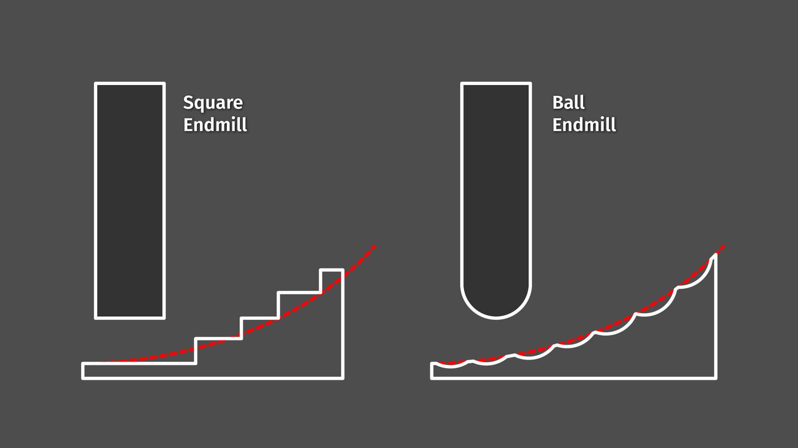
The larger the radius, the smoother the transition between the steps. And every bit of smoothness we can achieve during milling saves us a lot of polishing effort later on.
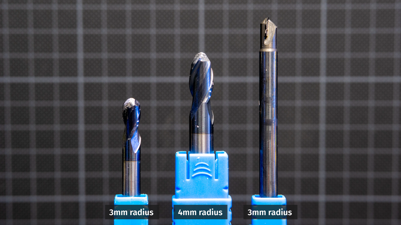
I did test two carbide endmills, a 2-flute 6mm endmill, a 2-flute 8mm endmill, and a single flute 6mm endmill with a polycrystalline diamond tip. All of these endmills were brand new so the flutes should have been nice and sharp.
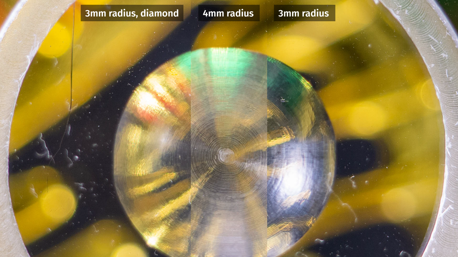
For comparison, I am looking at the acrylic surfaces right off the CNC and surprisingly the 3mm standard endmill looks best. Maybe that’s an issue with my speeds and feeds, so take this with a grain of salt.
Toolpaths
Anyway, let’s talk about toolpaths before moving on. I am using Fusion 360 for CAD and CAM and Fusion is basically giving us three different options:
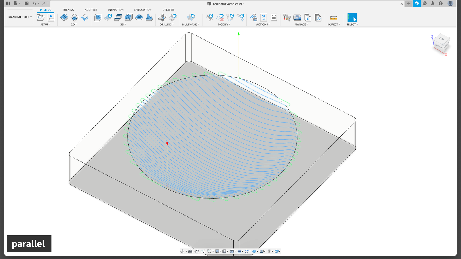
A parallel toolpath, where the tool is just going back and forth in lines, varying the depth of cut.
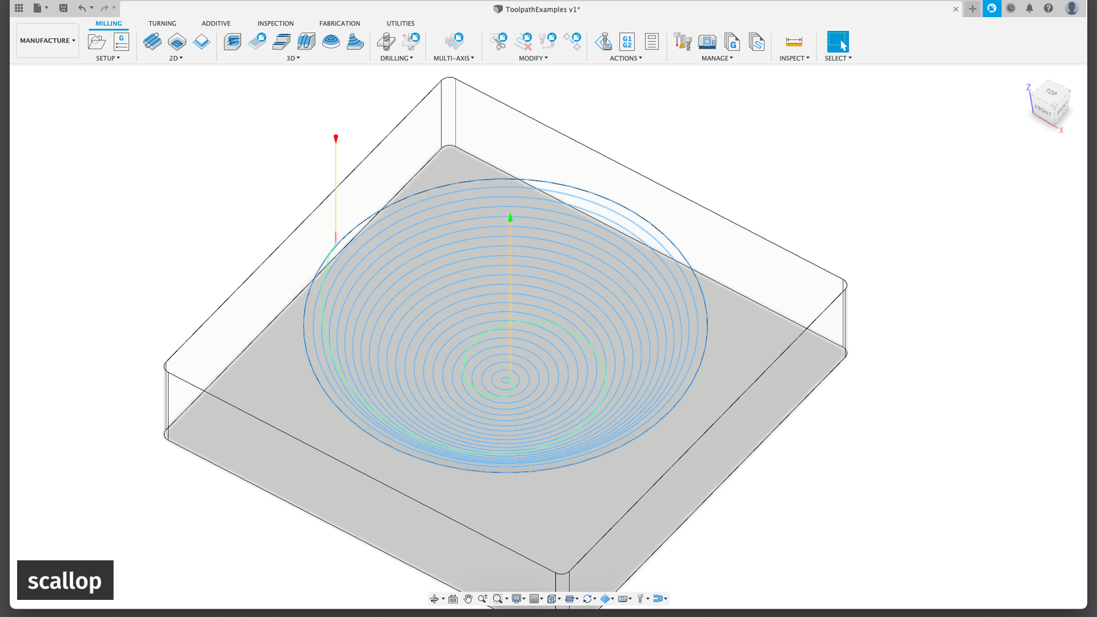
A scalloping toolpath, going in circles, lifting the tool after each circle.
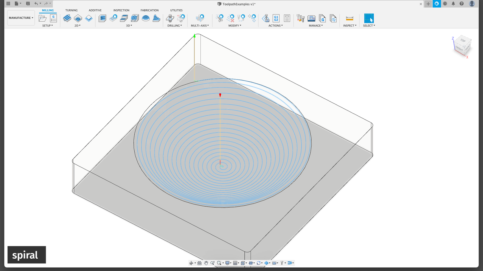
A spiral toolpath, lifting the tool continuously while spiraling.
But when looking at a few test pieces I couldn’t see much of a difference, so I am sticking to spiral.
An additional note: I am using a home-built CNC mill here. That’s certainly not a perfect machine. It has a non-negligible amount of angular error in all axes, there is a tiny bit of miscalibration in the steps per mm and it has some backlash. Basically, it’s what you would expect from a CNC machine at home. This does in a way affect what makes sense and what doesn’t. The error by the machine may be considerably larger than the difference between endmills or toolpath strategies. But the result is pretty clear: both the general shape and the surface quality directly off the CNC are not perfect. For example: I am not quite sure who’s to blame for this circular pattern:
Maybe it’s Fusion360’s toolpath settings, maybe it’s Fusion’s Gcode generator, or maybe it’s my CNC controller. I still need to remove a bit of material to even out the spherical surface and get rid of the scratches afterwards.
Grinding
With a proper CNC or a lathe you can just go directly to polishing and the important part is only that the polishing tool follows the existing surface as closely as possible. But when the geometry is not perfect yet you need something you can use as a tool and it needs to have exactly the curvature you want in the end, just inverted or mirrored. The most precise spherical surface I could find for a reasonable price was: precision ball bearings.
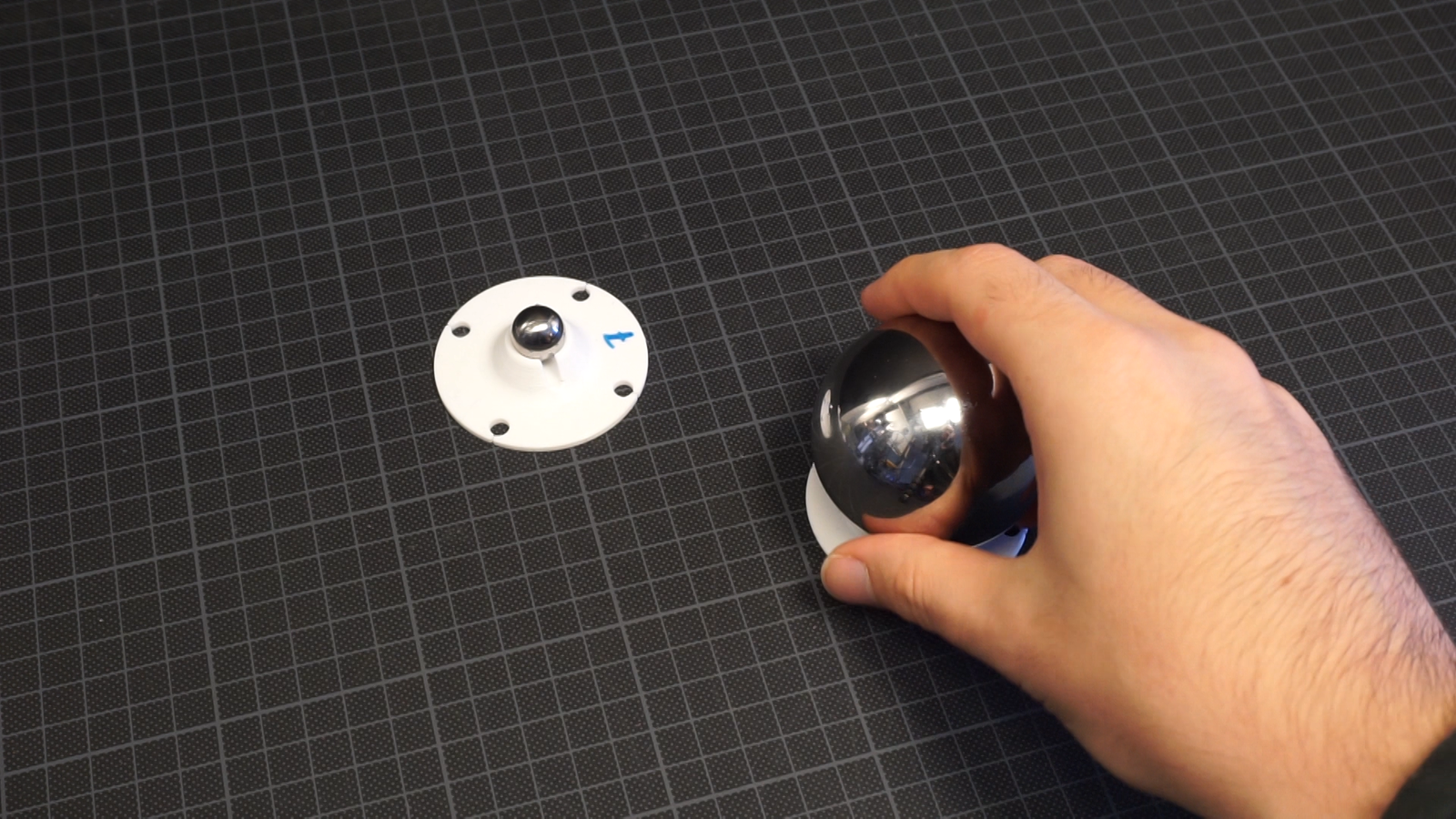
That’s hardened steel or ceramic, you’ll find quite a decent collection of different sizes and you can buy even the larger ones in small quantities pretty easily. Perfect.
Next step: to actually grind and polish the material some abrasives are needed.
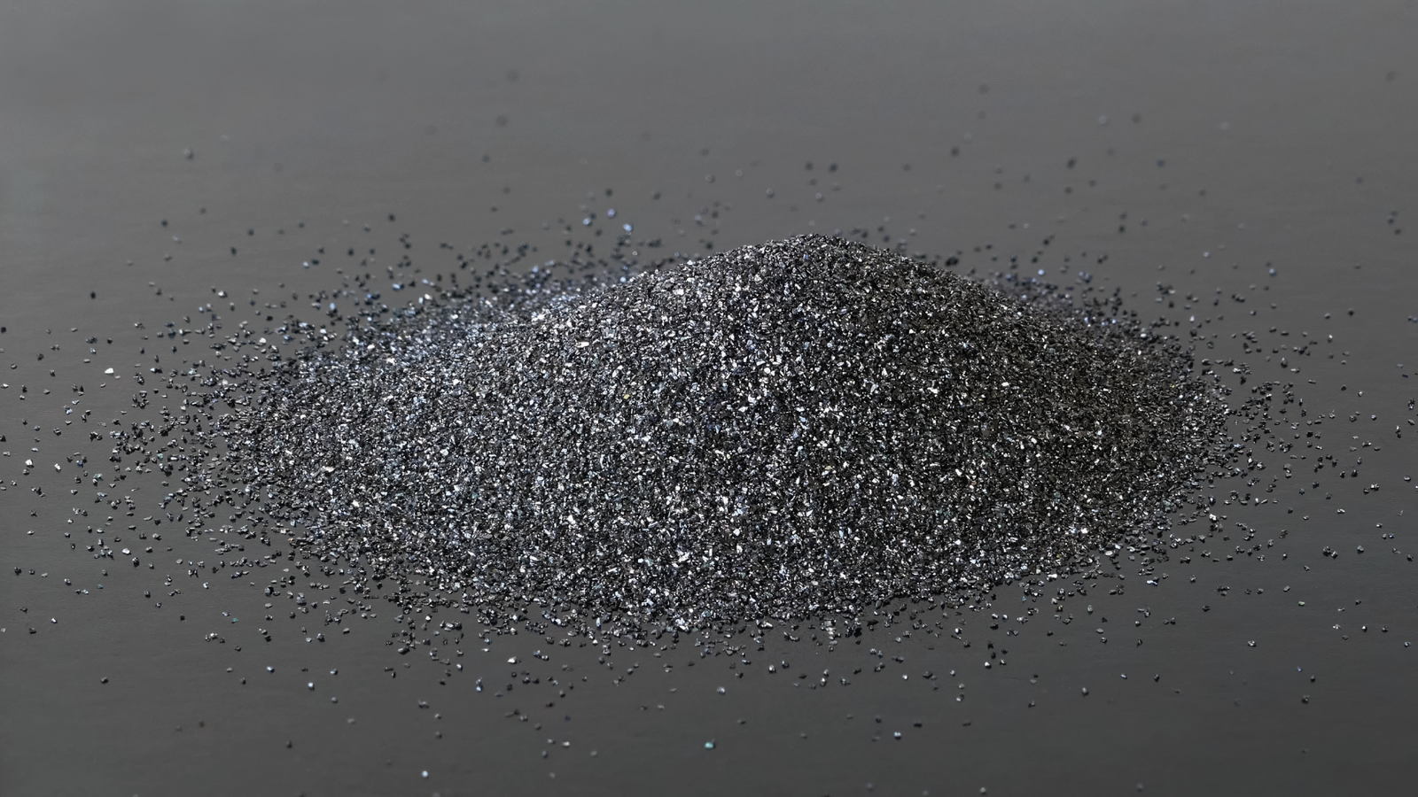
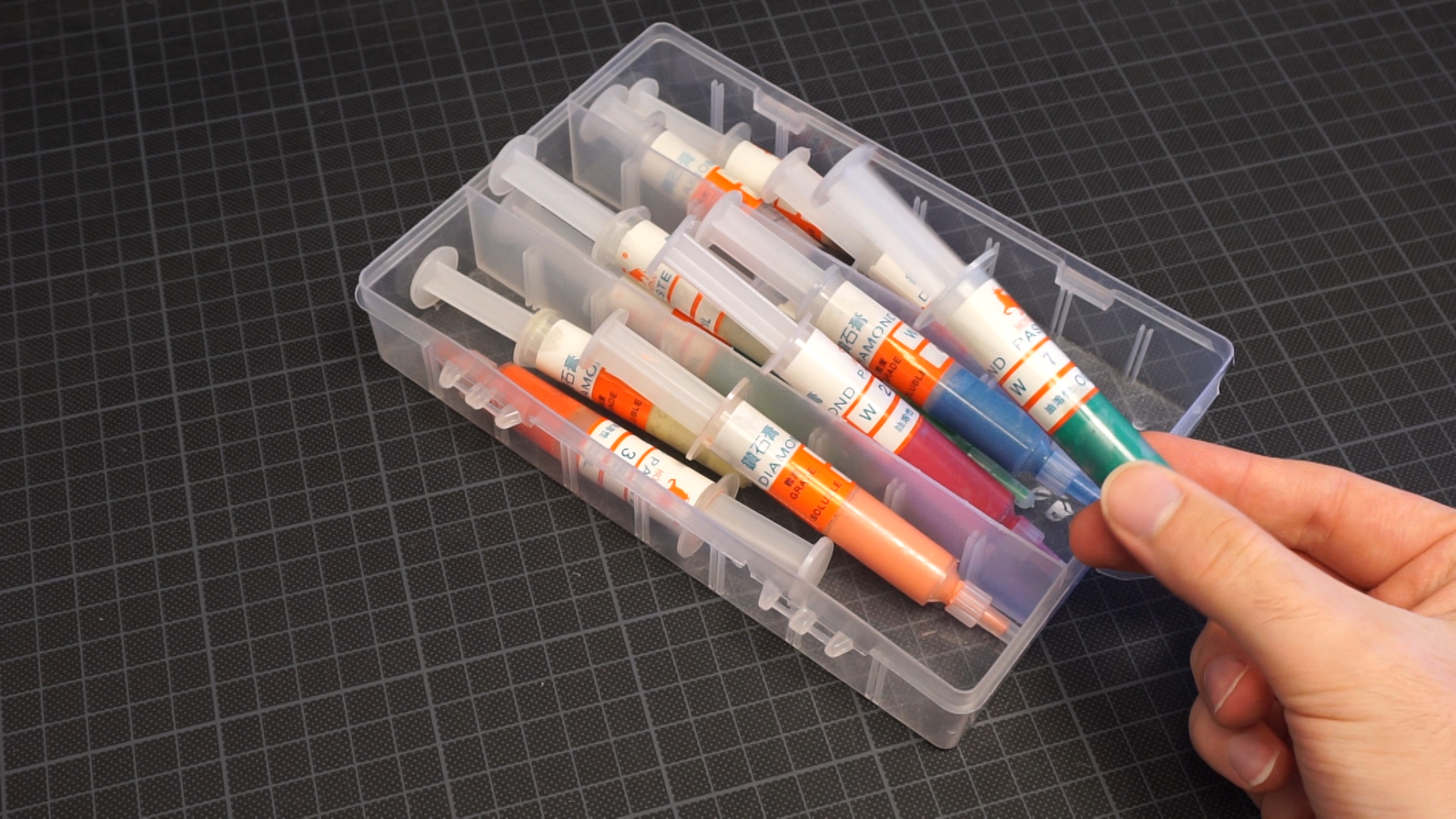
Usually people will use silicone carbide and cerium oxide for glass, maybe something cheaper like aluminium oxide for acrylic. That’s what’s used in many acrylic polishing creams. But it’s pretty hard to get small quantities of these abrasive powders. Shopping around on Aliexpress or Amazon you can find lapping pastes with diamond particles. These are pretty expensive per gram compared to powders and probably overkill, but I won’t need much so that’s what I used.
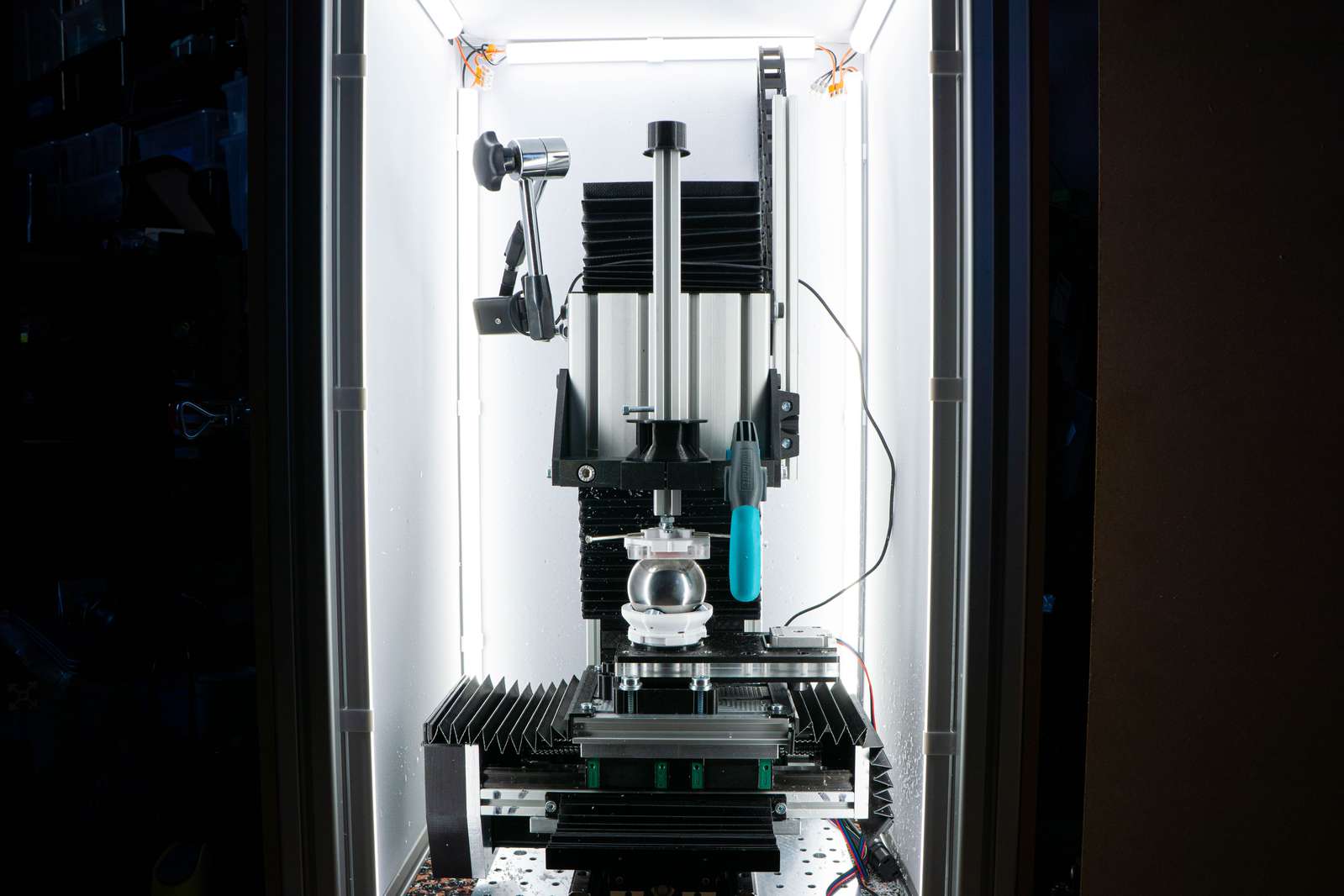
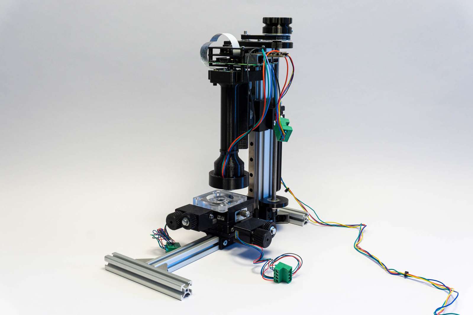
Now we just need to press the bearing ball against the mold and move it for a few hours. Of course, I have very little interest in doing that manually so let’s modify a machine for that. You can use whatever you got, there is very little force involved, so a cheap 3d printer with a few additional printed parts totally does the job. I am using the CNC because that was the easiest option. I just remove the spindle and screw a fourth stepper motor to the bed which can spin a piece of plastic with the ball.
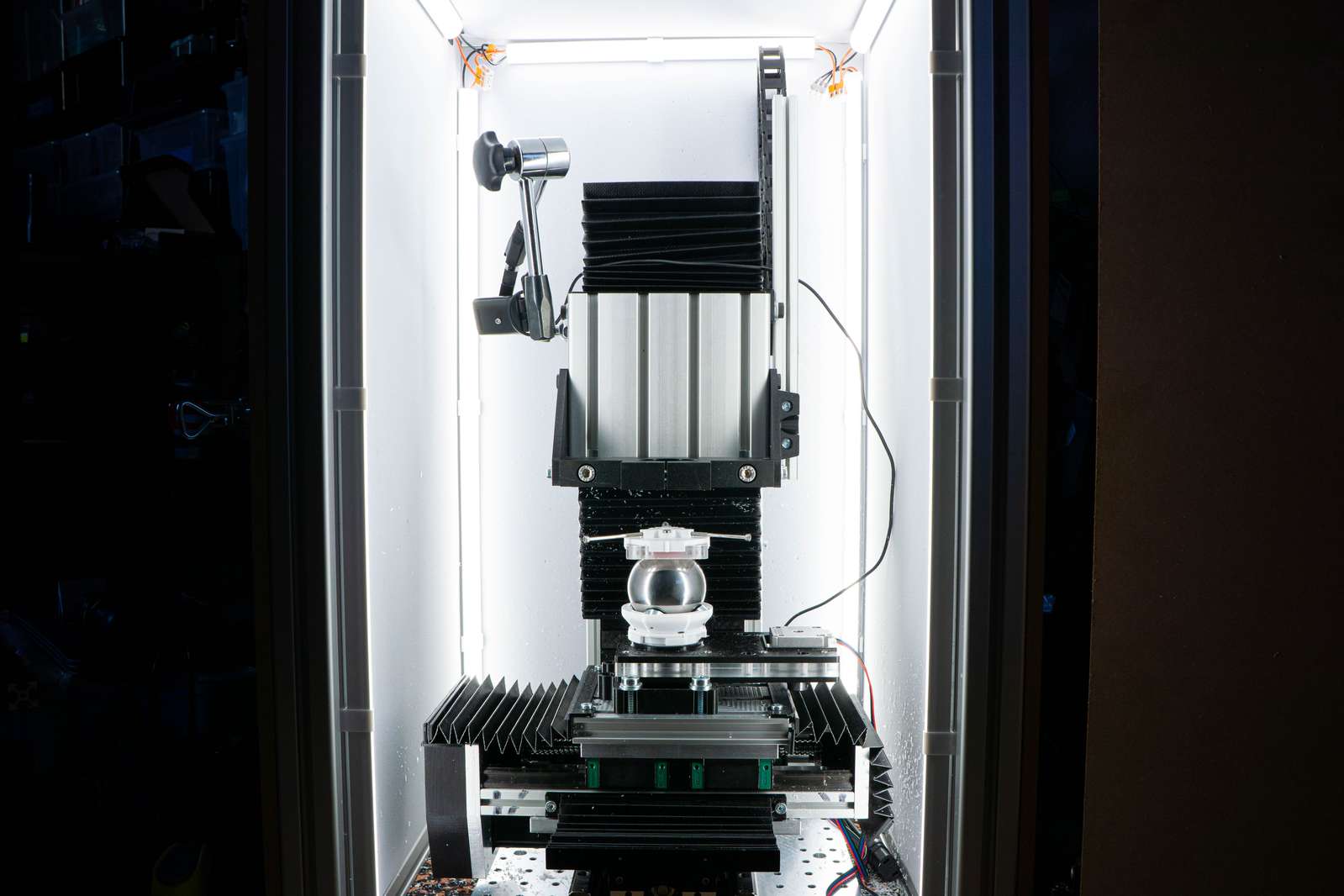
Instead of the spindle, I put a holder on the Z column that can slide up and down. The holder presses the mold on the ball bearing and has a ball joint so the mold can tilt. I am using a clamp to prevent the mold from spinning and a small weight on top of the holder but be careful, too much pressure prevents the parts from grinding properly.
If it’s working as expected you can actually hear the grinding.
I wrote a small script to generate gcode that moves the X and Y axes in a circular pattern to change the center of rotation.
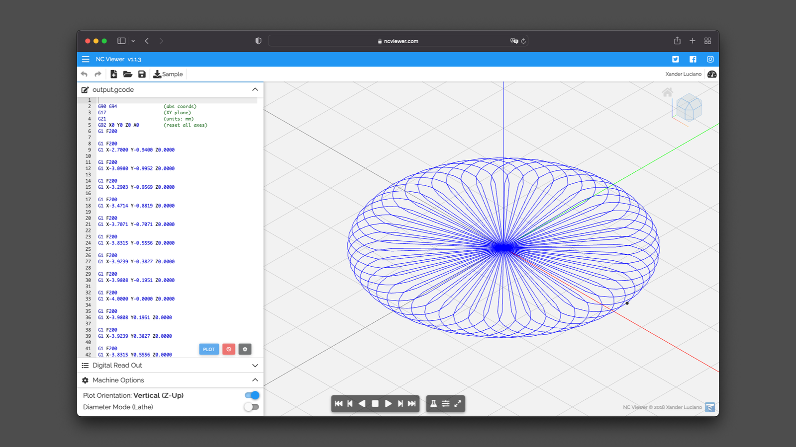
If the table would not move the ball sideways, it would look something like this:
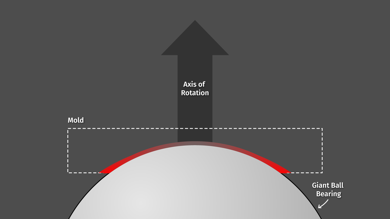
the ball bearing spins and would move the lapping paste at a high speed across the circumference while the center would not move at all.
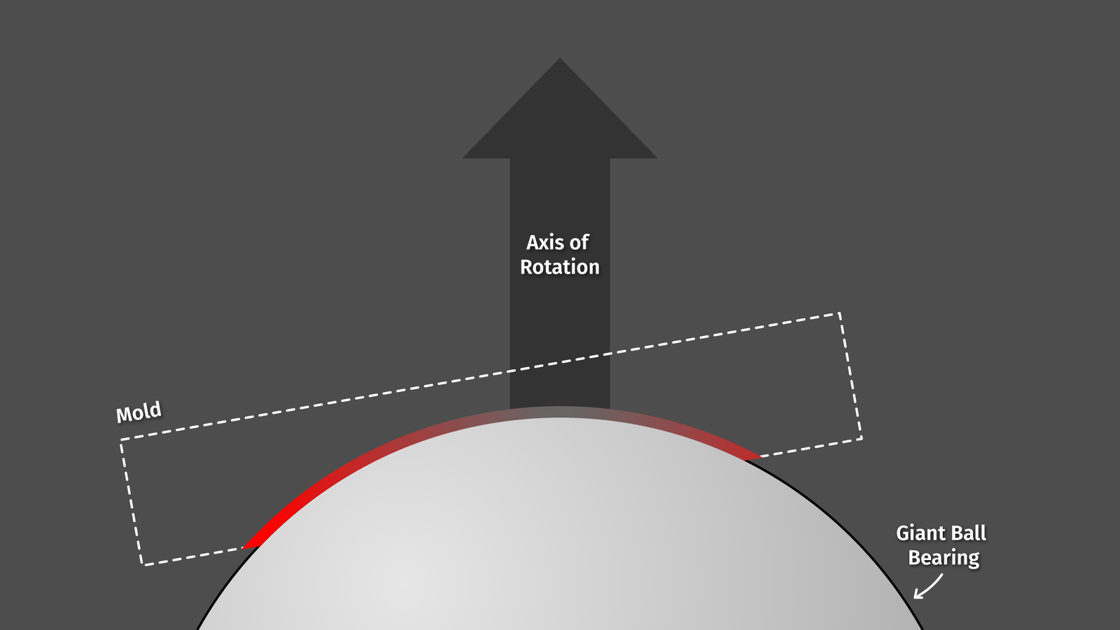
When I move the ball bearing while spinning I can reduce that difference a bit. That’s how it looks in action:
Of course, this whole setup will still not result in a perfectly even polishing action across the whole surface, but I guess it’s good enough.
The first and largest size, 40 microns, takes forever because the shape of the cavity is not perfectly spherical and the ball bearing needs to grind it down a lot before it makes contact evenly. But once that’s done about an hour or so per grain size is more than enough.
Once in a while, I am removing the mold, cleaning it, and putting it in front of a camera and under a microscope. Quick note: one thing that’s pretty annoying about acrylic: you shouldn’t use isopropanol for cleaning, that’s creating micro cracks in the surface. Soap and water works well. Giving it a look under the microscope is a bit tricky because microscope objectives have a very shallow focal plane and the surface we want to inspect has a pretty decent curvature. One solution to that is simply to put the lens on a motorized macro slider and do some focus stacking.
More info can be found here.
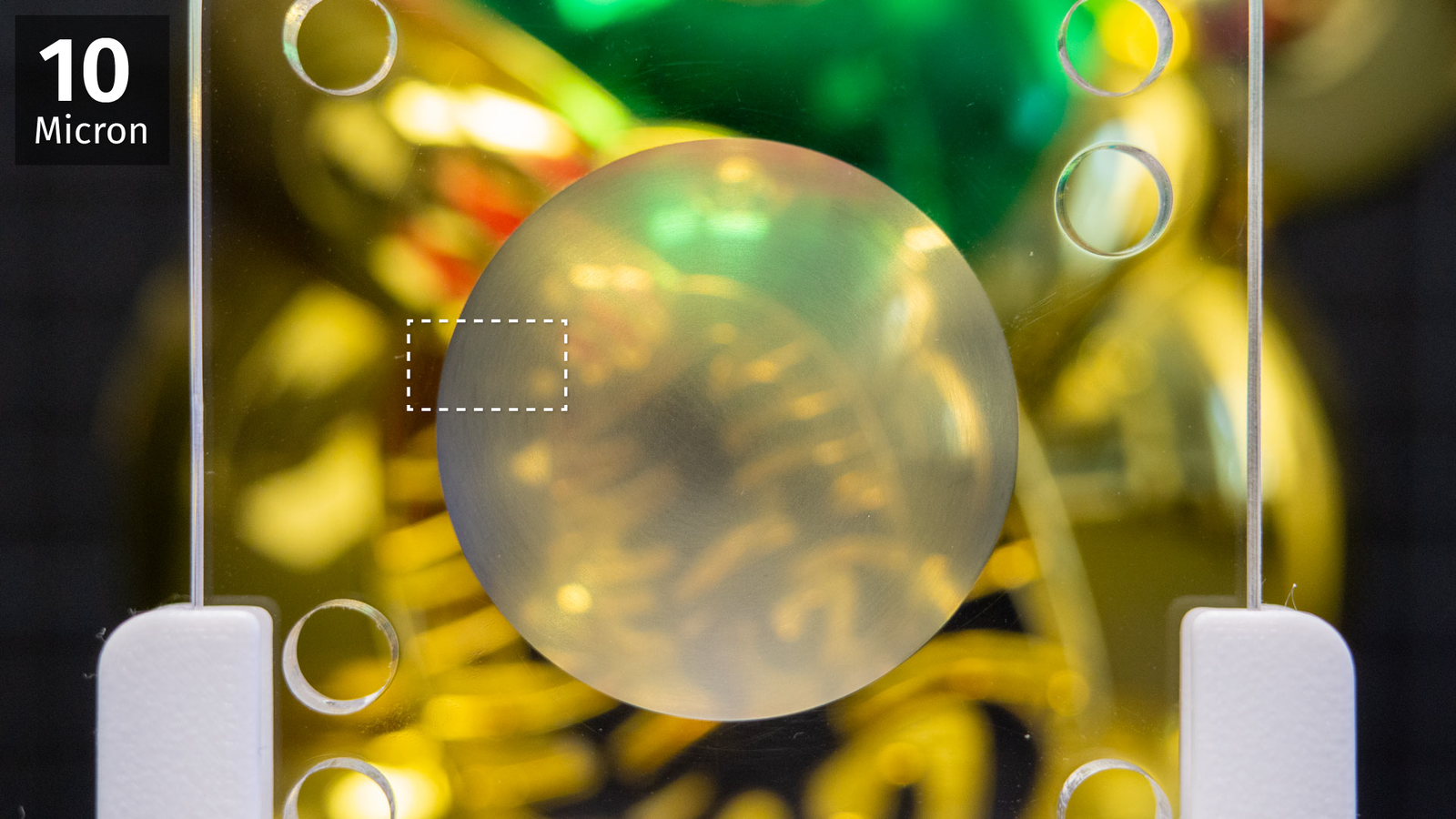
By the way: we will be looking top down on this section of the part. In the microscope image we see that the rough surface reflecting the light gets finer and finer.
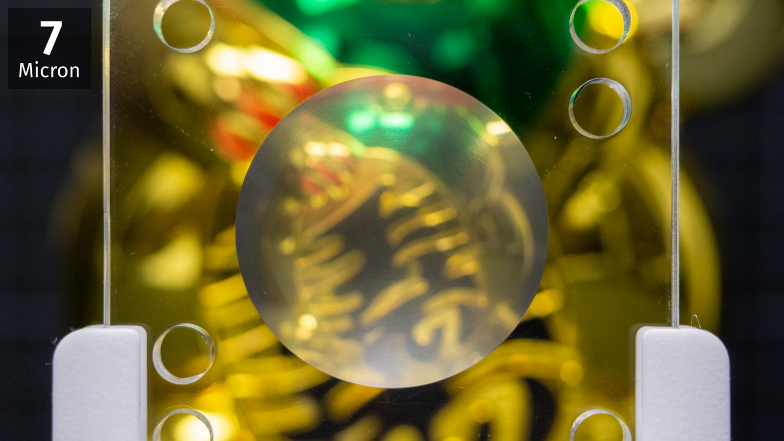
At 7 microns (image below) the acrylic is beginning to clear up, both on the camera and under the microscope. When all the scratches from the previous grain size are gone, we can move on to the next one.
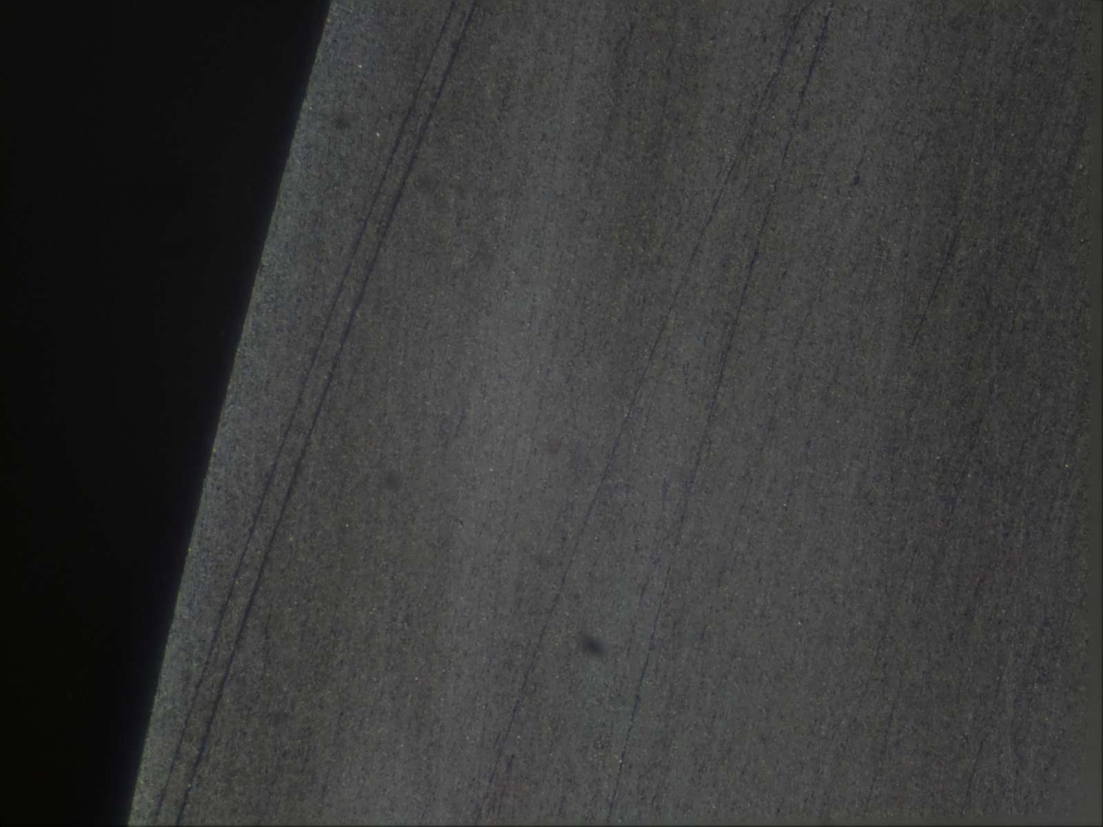
When we go smaller getting rid of all the particles is not so easy. I lost a lot of time and I had to go back several grain sizes because I got big, fat scratches on my nice surface:
In the end, I just 3d-printed the part which holds the ball bearing several times and just use a fresh one when switching to smaller particles. Adding magnets to prevent the ball from moving helps to keep contamination to a minimum as well. Sometimes the lapping paste needs a bit of thinning so the oil film with the diamond particles is as thin as possible. I used WD-40 for that but probably any other mineral oil would work as well.
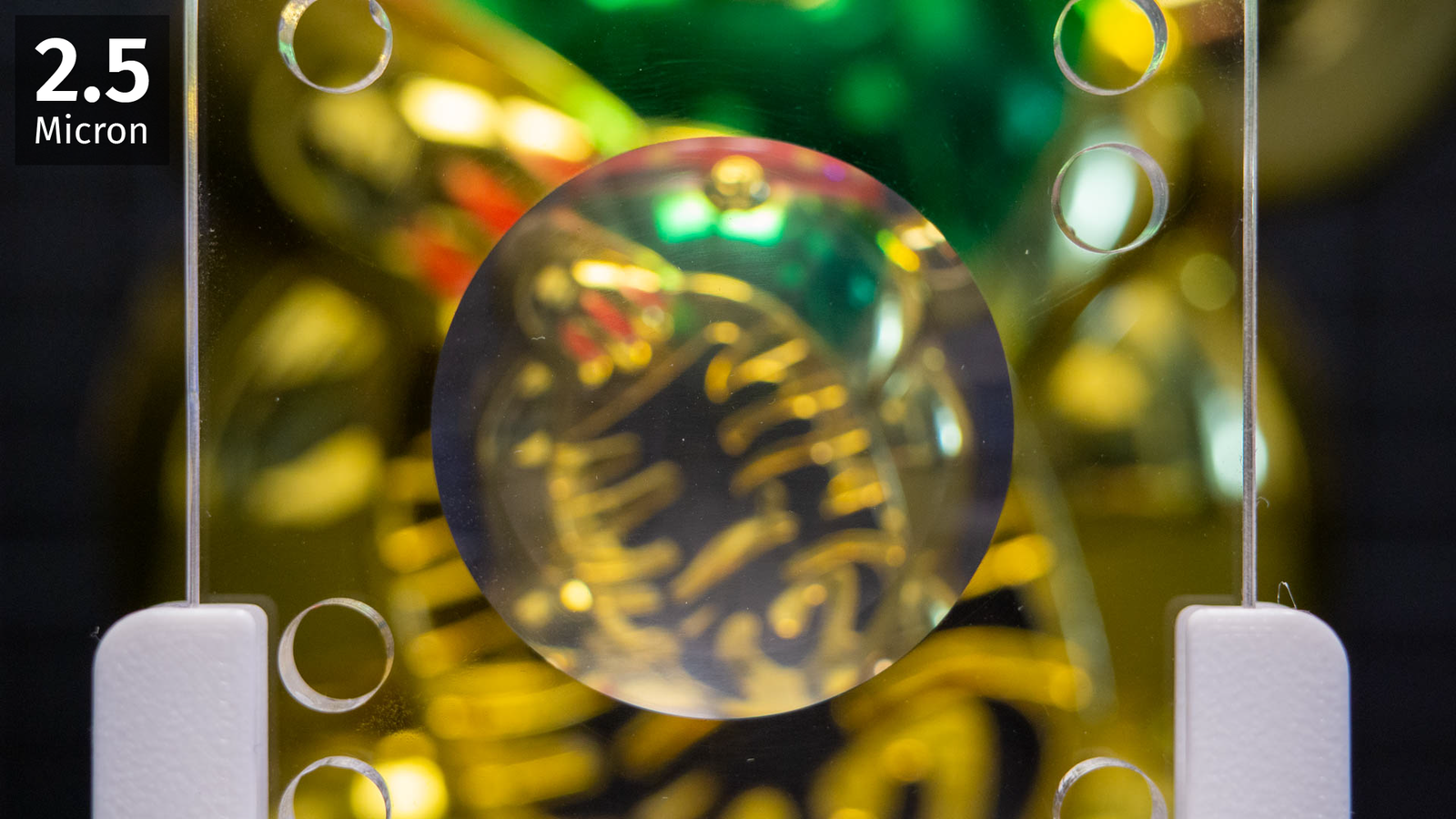
Eventually, at 2.5 microns I stopped. The surface is not perfect, you can still see the fogging and a bit of larger scratches if you look closely. Probably there is a limit to what you can achieve here anyway. Usually, when polishing or lapping, the tool should be softer than the object you want to polish. For example, when polishing lenses people use pitch which is technically not even a solid material. It slowly deforms and exactly mimics the shape of the surface. In our case, it’s the opposite, both aluminium and acrylic are softer than hardened steel and that may be an issue at this small scale. I am very sure that the uneven material removal rate will have made this surface slightly wider around the rim. But I have neither tools nor knowledge to measure the deviation from a sphere perfectly but it’s obviously lightyears ahead of my hand-polishing attempts. I am gonna use the lens molded off this thing as a spherical singlet, so the imaging errors everywhere off-center would already be clearly visible even when the lens would be perfectly manufactured.
Silicone
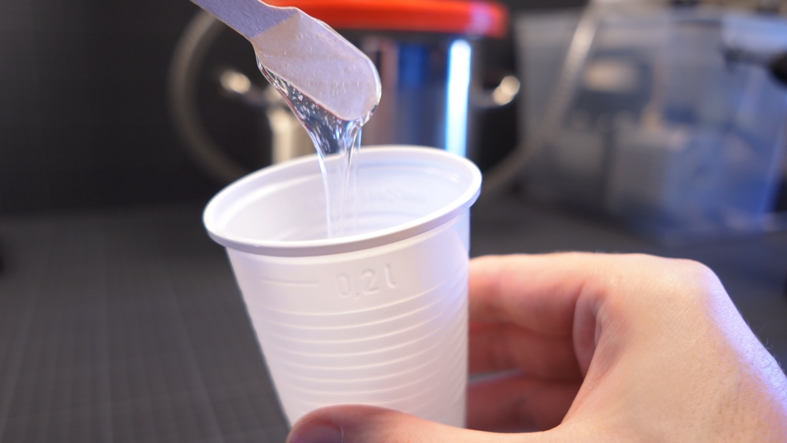
Last step: make it squishy! I’m not gonna talk too much about pouring silicone, there are people who explained that way better than I could. Just the basics: we mix both components of the silicone and put that in a cheap vacuum chamber to remove the air bubbles, sadly that step is not optional. Once it’s degassed, we pour it and wait a few hours before removing it from the mold. That’s all. But we actually need a silicone that’s optically clear and reasonably soft and that’s more of an issue.
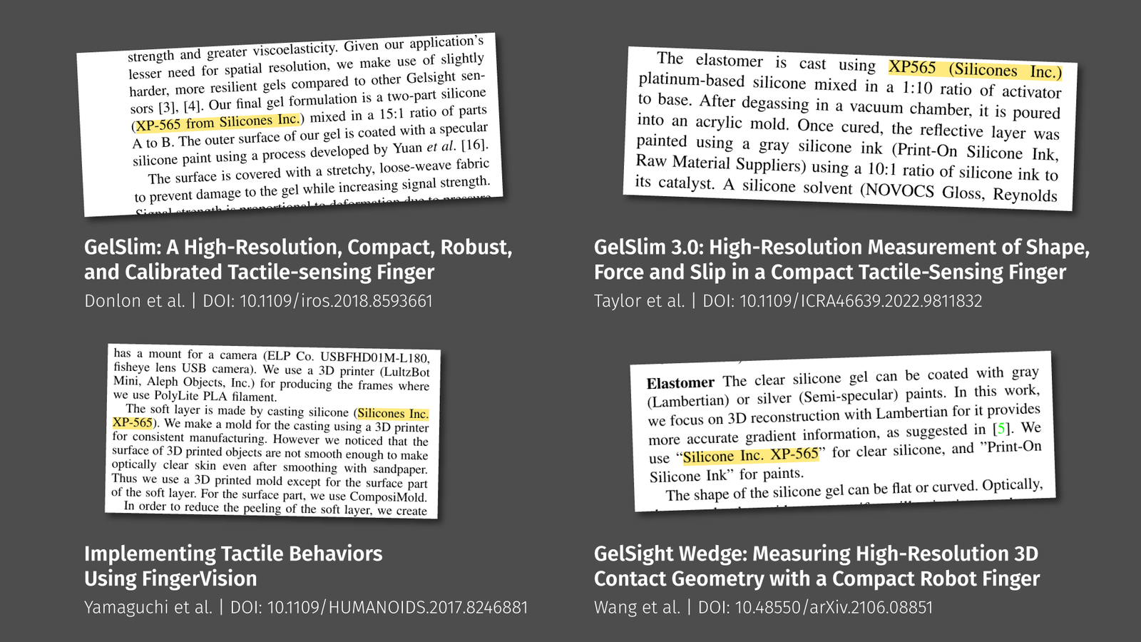
A lot of research papers that did something with soft optical sensors use a platinum-cure silicone called XP-565 by the company Silicones, Inc. but that was impossible to purchase for me in Europe. Some other researchers use Smooth-On’s Solaris, that’s a potting silicone, made for sealing solar cells and electronics, so it’s reasonably clear. Sadly that stuff was just absurdly expensive. The problem in general is that many silicones you find online are in some way described as translucent, transparent, clear, or optically clear, but only in the last case you can be sure about what you get. But even then… I tested one that looks pretty good at first glance, SILGLAS 25, but it is marketed as special effects silicone because it is extremely brittle and breaks like ice.
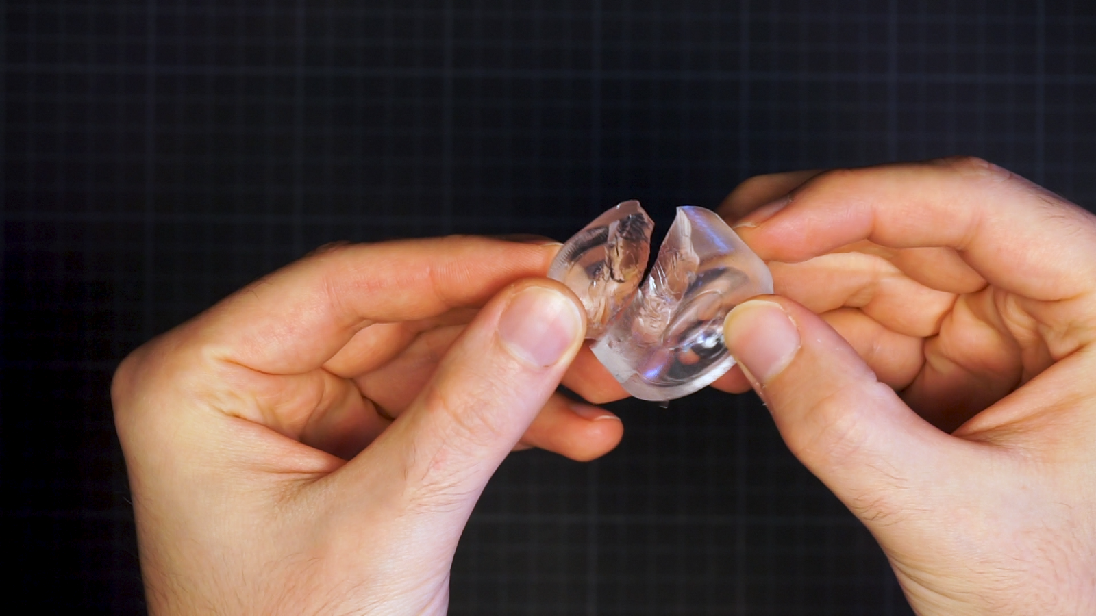
Sadly, that’s not what I need. After a few more candidates I settled on Trollfactory’s Type 19. Clarity is sufficient, price is okay-ish and it’s mechanically robust. The only problem: it’s very viscous and a bit fast-acting.
You got about 5 min for mixing, degassing, and pouring once you added the catalyst to the base component. Anyway, if you are in Europe, that may be your best choice.
But the problem with highly viscous silicone is getting rid of the trapped air. That’s true for both the bubbles created by mixing the components and the air trapped in the mold when pouring. I decided that I don’t want to use any thinner for the silicone and just fill the mold in the vacuum I need for degassing anyway. That’s not perfect since the vacuum pump I am using does only achieve about 90% of a vacuum or so, but it helps. For that, I built this simple contraption of a cup clipped to a servo motor that perfectly fits inside my vacuum chamber. It’s a Raspberry Pi running on a powerbank, so I don’t need to put any holes in the vacuum chamber for cables.
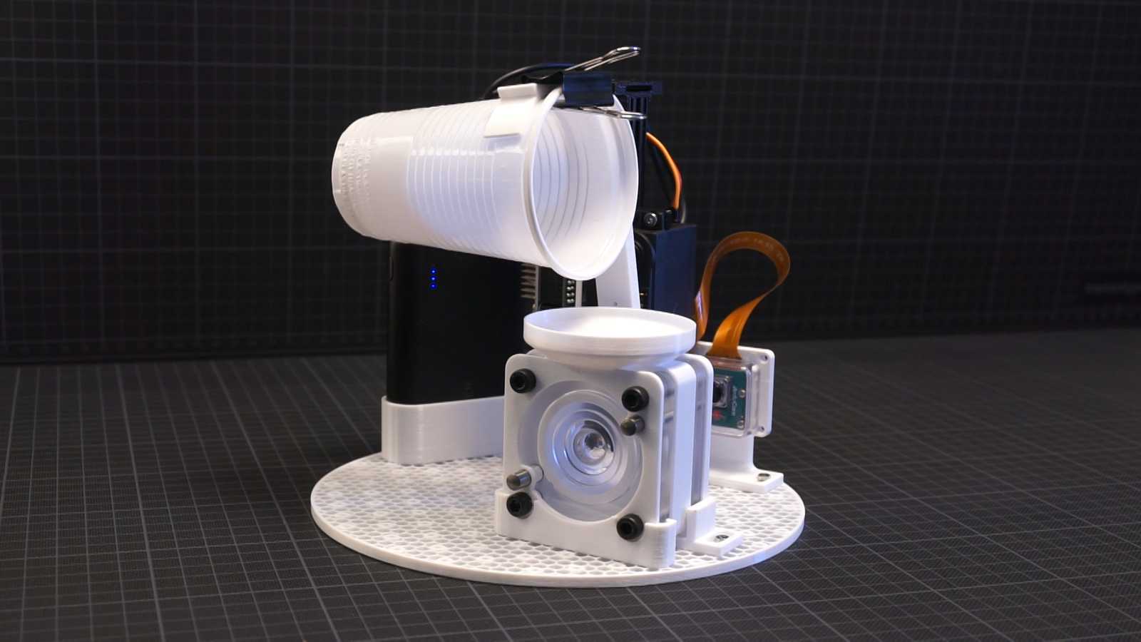
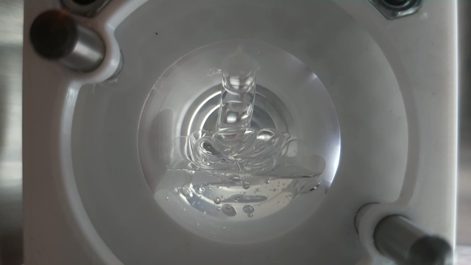
Bonus: there is a camera to actually watch the pouring progress in the acrylic mold. I am using an Arducam Hawkeye camera for the Raspberry Pi that actually supports autofocus. Pretty convenient for testing. So I just measure and mix the silicone and put it in the chamber. The vacuum pump takes about a minute to empty the chamber and the bubbles start rising on the surface. Once enough air is gone, I tell the motor to move the cup and pour the silicone into the mold. There are still a few bubbles, but doing a two or three cycles of pressurizing and removing the air again gets rid of those as well.
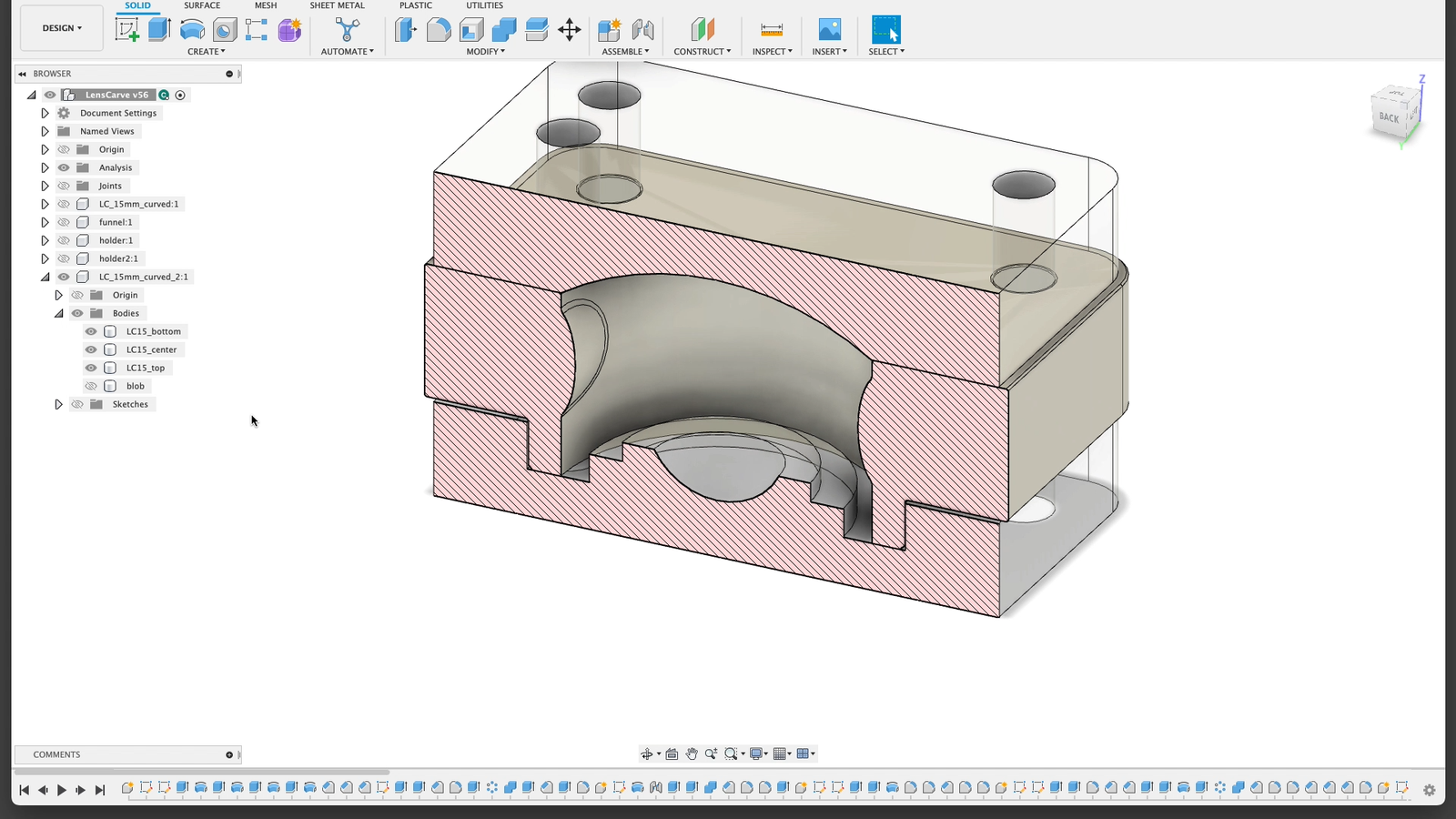
Once that’s done, it’s waiting for a few hours, and then removing the lens from the mold. I am using a 3d-printed part as a spacer for this mold because only top and bottom need to be really precise and I don’t care about the optical quality of the side of my lens. All parts of the mold are aligned with dowel pins and fixed with screws. That was the simplest design I could come up with.
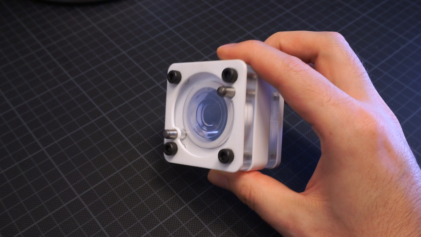
So, that’s my flexible lens:
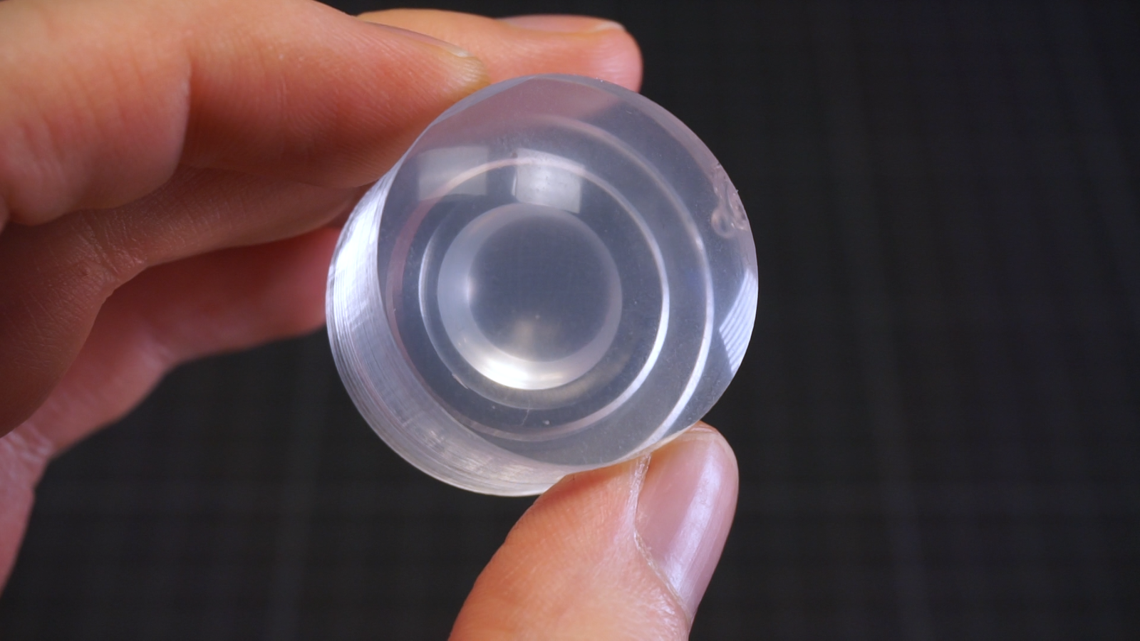
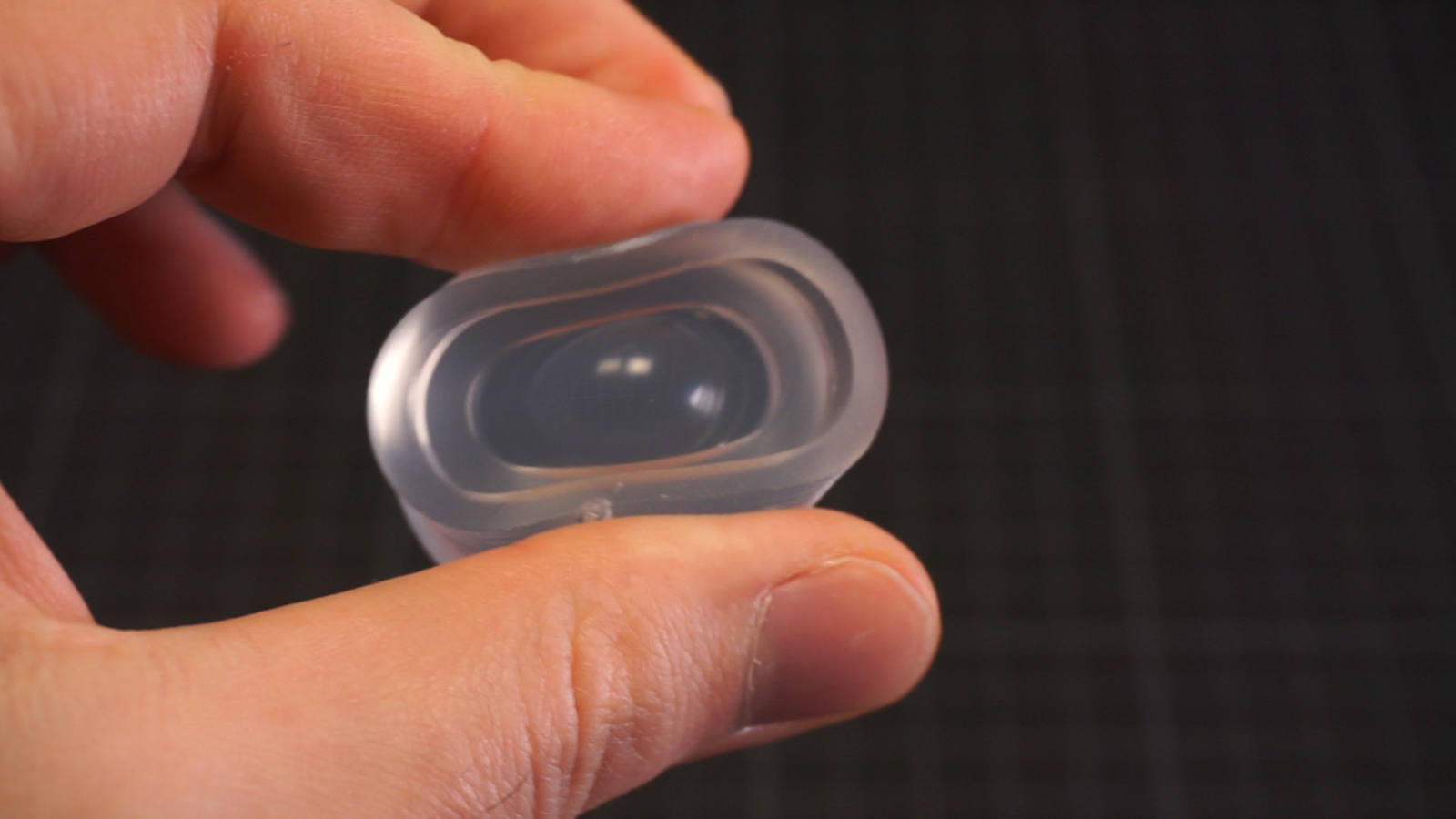
You can see a slight white-ish tint, that’s the cheap silicone. The lenses look pretty clear, the liquid silicone of course will be a bit forgiving and not perfectly replicate the tiniest scratches found in the optical surface. Everything smaller than a micron or so will probably be gone, maybe a bit more given the viscosity of this particular silicone. That’s a part of the reason for my “good enough” approach. Another reason is that the resulting lens will be flexible, so the dimensional accuracy requirements are kind of low anyway.
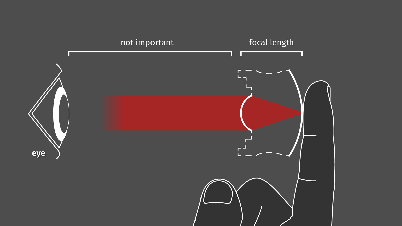
In case you are wondering what this lens is supposed to do: The first surface of the lens (the one on the left) has a focal length that is equal to its width. Any light reflected by objects touching the other surface will be exiting the lens collimated. Basically, that means that we got a squishy magnifying glass that works at any distance as long as your camera or your eye is focussed at infinity.
Taking it from here:
Given this technique we can make optical quality (to an extent) molds for silicone. But if you made the part from acrylic you can directly use it as a lens with a negative focal length as well. If you made it from aluminium, you can use it as a tool to grind and polish another CNC-milled part with a positive focal length. Errors may add up and increase in the process, but you get the gist.
Usually I am publishing CAD files and code as well for my projects because someone might find it useful. In this case I am not doing that because the attachments to my CNC mill or the makeshift vacuum pour contraption will only work with the stuff I use. But sometimes (especially when global supply chains go haywire) it’s hard sourcing the part one needs, that why I am listing this:
Where did I get the materials?
I am located in Germany, depending on where you live the following section may be helpful or not work at all for you. Some of these links will slowly become obsolete over the next weeks, months, and years. These are not affiliate links, I do not earn any money if you buy something.
| Part | Details | Price | Link |
|---|---|---|---|
| Vacuum chamber + pump | Generic vacuum pump VP115 | 155.75€ | https://www.silikonfabrik.de/detail/index/sArticle/513 |
| Trollfactory Type 19 | Clear silicone, Shore A19 | 35.90€ | https://trollfactory.de/produkte/silikon-kautschuk/haertegrad-shore/weich-shore-a25/7056/tfc-silikon-kautschuk-typ-19-glasklar-transparent-shore-1-1-special-effect |
| Acrylic glass | Acrylic plate GS - 10mm | 7.50€ | https://www.modulor.de/acrylglas-gs-transparent-farblos-10-0-x-120-x-250-mm.html |
| Endmill Ball | Carbide, 2 flutes, 6mm shaft, 3mm radius | 4.30€ | https://www.aliexpress.com/item/33057790604.html |
| Endmill Diamond | Polycrystalline diamond, 1 flute, 6mm shaft, 3mm radius | 31.66€ | https://www.aliexpress.com/item/1005002682469375.html |
| Diamond lapping paste | 40-0.5micron, 12 grain sizes | 12.00€ | https://www.amazon.de/gp/product/B08297Y41V (can be bought directly from Aliexpress as well) |
| Ball Bearings | 15mm / 60mm, hardened steel (1.3505), precision G40 | … | https://www.kugel-winnie.de/ |
| Magnets | Ferrite pot magnets, CSF-25 (for the large ball) | 7.75€ | https://www.supermagnete.de/eng/pot-magnets-ferrite/ferrite-pot-magnet-25mm_CSF-25 |
| Magnets | Neodymium ring magnet, 10/7 mm (for the small ball) | 4.40€ | https://www.supermagnete.de/eng/ring-magnets-neodymium/ring-magnet-10mm-7mm-3mm_R-10-07-03-DN |
Related things:
- Making a lens using a CNC mill by whitequark
- Liquid lenses and electrowetting by Applied Science
- CNC milling glass plates and mirrors by Applied Science
- Resin lenses in silicone forms by Jaycon Systems